|
How to Build a Telescope ?
|
CONTENTS
|
Glossary of Symbols |
1.1 Scope
1.2 The Newtonian Reflector
1.3 Shape of the mirror
1.4 Summary of materials required and procedures to be followed
2.1 Materials
2.2 Preparations
2.3 Rough Grinding
2.4 Chexking the sagitta
2.5 Finishing rough grinding
2.6 Fine grinding and smoothing
2.7 Testing the focal length and the mirror surface
2.8 Pitfalls during grinding and smoothing
2.9 Records
3.1 Preparing the pitch
3.2 Preparing the pitch lap (pitch tool)
3.3 Polishing
4.1 The Foucault or knife-edge test
4.2 Interpretation of the Foucault images
4.3 The fringes and their interpretation
4.4 Testing procedures and retouching
4.5 Aluminizing
5.1 The telescope tube
5.2 The mirror cell
5.3 The diagonal and its holder
5.4 The eyepiece
5.5 The eyepiece/diagonal support assembly
7.1 Collimation
7.2 Setting up and using the telescope
7.3 Troubleshooting
7.4 Care and maintenance of the telescope
|
Introduction |
The aim of this book is to describe how a simple reflecting telescope can be made with the materials and facilities available in India. As the primary goal is to popularize telescope making, only the most primitive (but effective) constructions will be considered; the emphasis will be on the practical aspects of telescope making.
Some excellent books on this subject are in print (see, for example, the Bibliography). Yet few people have easy access to these books as they are shelved in specialist libraries or are expensive to buy. Moreover, the methosds discussed are beyond the means of even most middle class Indians. Perfection, indeed, demands the use of thick glass perspx blanks, well graded abrasives, good pitch, sturdy mounts, good eyepiece etc. But a keen beginning amateur can make a useful telescope with which he can see many clusters, nebulae and other interesting objects, using rather ordinary materials. It is for such an amateur that this book is meant.
We shall only consider Newtonian reflecting telescopes of large focal ratios using simple altazimuth or german equatorial mounts. We shall not discuss parabolizing of mirrors, the construction of Cassegrainians, the design of telescope drives etc. These pages would have served their purpose if they encourage beginners to construct simple telescopes for sight seeing the skies. If they make this important beginning it is likely that in course of time they will become serious amateurs for whom the more advanced books will be indispensible; especially recommended is the book by Texereau.
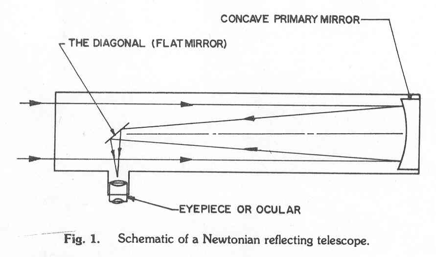
The schematic of a Newtonian Reflector is shown in Fig. 1. It consists of three optical elements : the concave primary mirror, the diagonal or small flat mirror and the eyepiece or ocular, mounted in a tube. The primary mirror gathers light from astronomical objects and focuses it in its focal plane. The small flat mirror turns the image around through 900 so that it can be viewed thorough the eyepiece. About 50% is of the labour involved in making a telescope of this type goes into grinding and polishing the primary mirror (Chapters 2 & 3 ). The other 50% is accounted for in the fabrication of the telescope tube, the mirror cell and the mount (Chapter 5 & 6). The eyepiece has to be bought readymade and the small diagonal is best obtained from a suitable source (e.g. the ABAA, the Association of Bangalore Amateur Astronomers).
We now define certain terms and symbols that will be used later. Let D and F be the diameter (aperture) and focal length of the primary mirror and let fe be the focal length of the eyepiece. It can be shown that the angular magnifying power of the telescope , M is given by
M= F/fe
Thus the angular magnification can be increased by increasing the focal length of the primary or by decreasing the focal length of the eyepiece; the latter is what is normally done when increased magnification is required.
Apart from its magnifying power a telescope is characterised by its light gathering power, which increases as the square of the diameter, D, and the resolving power which also increases with D. In brief, a telescope�s power to see faint objects increases greatly with the aperture D of the primary mirror.
A term commonly used in the trade is the focal ratio, F/D, of the primary. When one talks about an f/8 (pronounsed �eff eight�) mirror, one means that F/D=8. For a given aperture, the larger the focal ratio the larger the focal length, the shallower the mirror surface. It is easier to make large f-ratio mirrors than to make small f-raito mirrors. We will in these pages restrict ourselves to mirrors with D<= 20 cm and focal ratios equal to or greater than 8. Note for example, an f/9 (�eff nine�) mirror whose aperture, D, is 15 cm will have a focal length F=9D=135cm.
When making a telescope our primary aim is to see faint objects and to see them as sharply as possible. Beginners often make the mistake of placing importance on magnification; in practice, crisp, sharp images are preferred to larger, fuzzy images. Magnification is secondary to clarity and resolution.
The ideal mirror is a paraboloidal mirror as it brings all rays parallel to its axis to a focus at its focal plane. A shallow spherical mirror (i.e. one whose focal ratio is large) is, however, a good approximation to a paraboloidal one and is far easier to make. It is for this reason that we shall only consider mirrors of focal ratio between 8 and 10 or 11; if the focal ratio is too large, the telescope tube will have to be long and unwieldy.
What should be the choice of mirror diameter and focal ratio for a beginner? Experience has shown that it is best to choose a mirror diameter of about 15 cm and a focal ratio between 8 & 9. Mirrors of diameter less than 12.5 cm and more than 20 cm are not advised; nor are focal ratios less than 8 or more than 10. Try sticking to these ranges for a start.
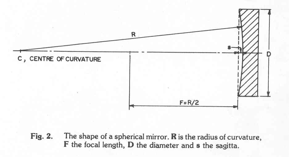
The shape of the spherical mirror surface is shown in Fig.2. For a mirror of given diameter D, the focal length is determined by the sagitta, s, the depth of the dish. Conversely, if we want a given focal length or focal ratio the sagitta is given by,
s= D2/8R=d2/16F= D/(16F/D)
For example, if we have a glass dish 15 cm in diameter and we wish to make an f/8 mirror, the sagitta would be given by
s= 15/(16*8)=0.117cm = 1.17 mm
It is not at all important that one obtain a mirror of specified focal length. One should only attempt to keep the focal ratio in the ranges given above. Once the glass blanks are obtained, the diameter messured and the focal ratio decided on, the sagitta should be calculated. Then a small piece (length less than 5 mm) of piano wire, drill bit, feeler gauge or steel rod whose diameter or thickness is equal to the required sagitta should be obtained and safely kept. This will be used during grinding to monitor the mirror shape. Also obtain and keep a gauge to measure say ¾ of the required sagitta. In this connetion note that a 10 p coin is about 1.70 mm thick, a 25p coin about 1.08mm thick and a 50p coin about 1.37 mm thick.
1.4 Summary of materials required and procedure to be followed
The following materials are needed to build a reflecting telescope
Round glass blanks � 2 in number.
Carborundum (silicon carbide) abrasive grit in about 6 grades from 120 to 1200.
about 20 small pieces of old, soft, cotton cloth (about 10 cm * 10 cm in size).
Jwellers rouge or cerium oxide.
Pitch, rosin and wax
Wood or PVC tubing for the tube.
Woodm pipes and pipe fittings, springs, nuts and bolts of various sizes for the mirror cell and mount.
More details of the quantities required and sources of supply will be given later. It is suggested that the work not be started until items (a) to (e) are all in hand.
Briefly, the following steps are involved in making telescope
Grinding the primary mirror.
Polishing and testing the primary mirror.
Designing and fabricating the telescope tube, mirror cell and diagonal suport.
Designing and fabricating the telescope mount.
Assembling, collimating and testing the telescope.
Working to the plan given in this book tasks (i) and (ii) can be completed in 30-40 hours for a 15 cm diameter mirror. Once the polished mirror has been sent for aluminizing, tasks (iii) and (iv) can be undertaken. Since a number of simple designs are given in this book this phase can be completed in a few weeks time. With the aluminized mirror in hand and the structural work completed collimation and testing can be done. If all materials are available, it should be possible to complete the telescope in 3 months time or less. Do not allow the project to drag on.
It is crucial that the work be done systematically and effectively and
efficiently. Before a particular task is taken up the preparatory work
for that task must be completed and a plan and time-table worked out. It
is suggested that this book be skimmed through rapidly once before mirror
polishing etc. is taken up the relevant chapter be read twice or check-list
is given in Table 1 for the whole project that might help to get the work
organized. In addition, it is important that a complete log book be kept
for the whole project.
|
2. Mirror Grinding |
The following materials need to be procured:
Material Quantity
a. Glass blanks 2 Nos.
b. Carborundum grit (silicon carbide)
80 grade ½ kg
220 grade 250 gms
320 grade 100 gms
500 grade 50 gms
800 grade 50 gms
1000 grade 50 gms
c. Ferric Oxide or Cerium Oxide 20 gms
d. Pitch
½ kg
Rosin
100 gms
Bees Wax
100 gms
The glass blanks, circular in shape, could be from ordinary plate glass but their thickness should be at least 1.2 cm for blanks upto 20 cm in diameter. These would be considered too thin by the standards of the authorities but in India it is difficult to get thick glass blanks and we have to make do with what is available. These have been found to be adequate in practice. The glass discs should be flat and free from blowholes (check by looking thorough them). It is recommended that beginners use blanks about 15 cm in diameter.
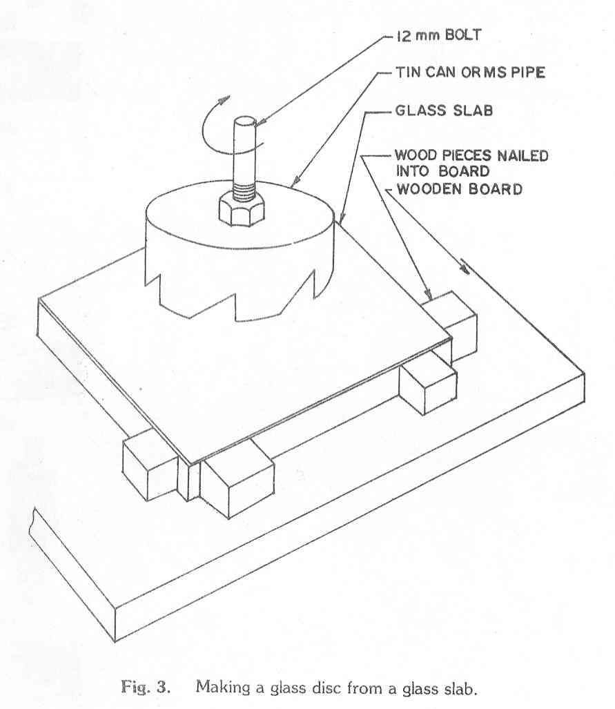
If one has access to a glass slab or plate of suitable thickness circular glass discs can be cut by the method shown in Fig. 3. the cutting tool can be made from a tin can (a milk powder tin for example) or an MS (mild steel ) pipe; it helps to have 4-6 teeth cut as shown , but their shape and size are not too important. The shaft can be a 12 mm bolt. The bolt can be driven by an electric drill press or even by an old fashioned bow drill used by carpenters. Cutting is done by feeding a watery mixture of 80 grade carborundum grit while the rotating tool is pressed into the glass plate.
Carborundum (silicon carbide, Sic) is a grayish black abrasive; emery, another commonly used abrasive, is a natural form of aluminium oxide. It is often recommended that rough grinding be done with carborundum (carborundum) while fine grinding be done with emery. We recommended that in India one should use whatever is available; amateurs have been known to do rough grinding with ordinary sand! As for the grades shown above the numbers are not critical : one could use 500 instead of 400 grit etc. In fact, what is sold in the market as a particular grade often turns out to be coarser or finer than claimed. Under these circumstances the best one can do is to get a range of powders from coarse to as fine as is available; a microscope, if available, would be most useful in comparing grain sizes. The quantities shown should be ore than adequate for making mirrors upto, say 15 cm in diameter. The powders should be kept seperately in clean labelled plastic containers, plastic bags or tins.
Rouge is a fine red powder, a form of ferric oxide, used by jewelers to polish jewellery. It has to be cleaned thoroughly before use as it is often sold in poor condition. Cerium oxide is much cleaner but not readily available.
Pitch, which is a kind of tar, is readily available in hardware stores. The quality, however, varies widely. When bought it should be hard enough so that when a finger nail is pressed into it the impression should not form too easily; it should not be brittle; it should be possible for a small piece to be chewed and stretched like chewing gum; it should not break when bitten. Rosin is a hard, brittle, crystalline, natural resin; it is used for hardening the pitch. Pure beeswax is obtainable from Bansari or Khandsari shops.
It is advisable, before starting the mirror grinding operation, to clean the rouge and various grades of carborumdum grit and to prepare a convenient work table. This will permit later operations to be smooth and efficient.
a. Cleaning the rouge : Bring to a boil approximately 20 gms of rouge in about 1 litre of water and let simmer for a few minutes; remove all the frothy scum that appears at the top. cool and strain through tow layers of fine cloth (e.g. dhoti material of 80-100 counts) into a clean jar, No.1. (e.g. a Horlicks bottle or a glass jam jar). Let the mixture settle for an hour or so and pour out most of the fluid on top and keep the thick sediment of rouoge at the bottom (still covered by, say, 2.5 to 3 cm of water). Shake well and strain through fine cloth a quarter tumbler of solution into a tall glass tumbler. Fill the tumbler with water, stir briskly and let settle for 1 minuter; then siphon off with a rubber tube the top half of the solution in the glass tumbler into another clean Horlicks bottle (No.2). This bottle will contain the rouge to be used. Fill the half emptied tumbler with water, stir, wait for another minute and repeat two, three or four times. Do the same with the rest of the material in bottle No. 1; it will be faster if one works with 2 or more glass tumblers. If bottle No.2 is full, another bottle could be used. Let the rouge settle in bottle/bottles No. 2 for a day, pour out the top half to two-thirds of water and keep the remaining rouge in solution. This can be then be used for polishing. Label bottle No.2 �1 minute rouge�. From the 1 minute rouge one could also prepare some 10-minute rouge by stirring and waiting for 10 minutes before siphoning. This will be useful for the final stages of polishing. Keep the 10 minute rouge in bottle No.3
b.Cleaning the carborundum grit : After cleaning the rouge, the carborundum grit has to be cleaned, starting with the 1000 grade and working down to 80 grade. Stir 1-2 teaspoons of grit in a tall glass of water for a few seconds; stop stirring and allow the grit to settle for t seconds and siphon off with the rubber tube the upper half of the contensts of the tumbler into a larger vessel, V. fill the tumbler with water again, stir, let settle for t seconds and siphon off the top half into vessel V. Repeat 5 or 6 times, then clean out the tumbler, add another 2-3 tea spoons full of grit and repeat. Let the mixture settle in V, then pur out the top water and transfer the clean grit, which will be in the form of a thick sludge into a small clean plastic container or bag or bottle. Label it clearly. Repeat with the other grades of grit. The following settling times have been found to be conservative but satisfactory :
Grit Size t seconds
1000 120
800 90
500 60
340
15
Note that
the times suggested above are just approximate; the worker, with a little
practice, can estimate reasonable times for other grit sizes if need be
or even reduce the above if practicable. Do not throw away the carborundum
left over in the above procedures; store the remains in labelled containers
as they may be useful later for coarse grinding, chamfering etc. To clean
the 80 & 220 grades, just stirin water and throw away the scum that
floats to the top. All grades of cleaned grit should be stored in small,
labelled plastic or glass bottles (or empty plastic milk bags) with just
1 mm or so of water covering the grit sediment. Remove all uncleaned grit
from the work area which should be kept very clean.
c. Preparing the glass blanks : It is very important that both the glass discs have a champher at least on the faces which are to be ground. Fig. 4A shows how a chamfer can easily be cut using a cast iron vessel (kadai) whose diameter is larger than the mirror diameter. Put the blank in the kadai, sprinkle some wet 80 grit (about 1 tsp full) about the edge of the blank and rock the blank about the kadai by a rotary motion. A 2-2.5 mm chamfer, can be cut in 15-20 minutes, remove the blank, wash the kadai and blank and repeat using 340 & 800 grit until the chamfer is smooth. the purpose of the chamfer is to prevent chipping of the edges during grinding. If the chamfer, on either mirror or tool , is worn during grinding it must be recut before proceeding.
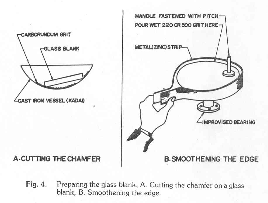
It is good practice to clean the vertical edge of the mirror blank if it is not smoth. This can be done with a flat carborundum stone or as shown in Fig.4B
d. Preparing the work post : From a flat wooden board or plywood sheet or perspex sheet 6-12 mm thick, cut a square work plate of side 5-10 cm greater than the diameter of the glass blanks. Centre one of the blanks on the plate and fix 3 cleats, approximately 12o) apart, about the blank leaving a gap of 0.5-1 mm; it should be possible to easily rotate the balnk within the cleats. The cleats, whose height should be less than the thickness of the blanks, can be fixed to the work plate using nails., screws or trichloroethylene (for perspex)
The work plate can be fixed to the work post in a number of ways illustrated for example in Fig 5. In Fig 5A & %B the work plate is held in position by wooden restraining cleats nailed to a table or to a wooden board resting on a kitchen slab; in Fig. 5C the work plate is screwed to the flange of a pipe concreted in a tub. It is an advantage, when cleaning the work post, to have the work plate easily removable from the post; a few sheets of newspaper below the plate also help to keep the post clean. It is best if the work plate is at elbow height at the work post.
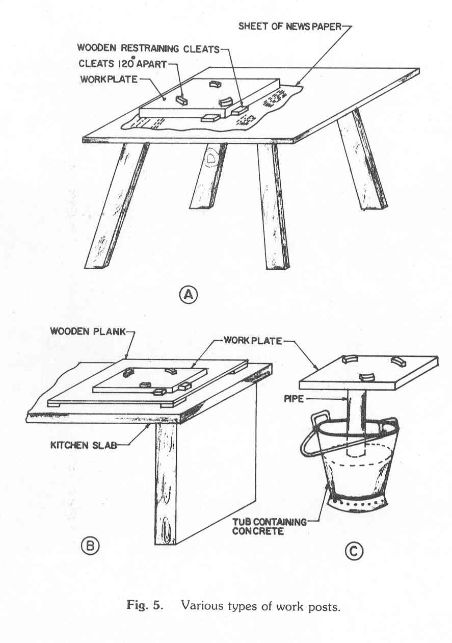
Before starting the grinding operation keep at hand tow pieces of cotton cloth (about 10-20 cm in diameter or side), a small tray or basin for carrying the mirror, a basin of clean water, and a heavy weight (4-6 kg for a 20 cm mirror, 2-3 kg for a 15 cm mirror, say) wrap in plastic or sheets of newspaper. The heavy weight, which could be on or two old bearings or a flat stone or an MS plate, should sit easily on the mirror and not hinder the grinding operation. The plastic bottle, with a plastic or wooden spoon for transferring the grit.
Choose one of the two glass blanks to be the tool; if the blanks are not of the same quality, let the inferior one be the tool. Position of the tool on the work plate between the cleats, with the chamfered edge facing up. Take ½ -1 teaspoon full of 80 grade carborundum and spread it over the tool face. Sprinkle a few drops of water form the finger tips and place the mirror about ¼ D from the centre of the tool (i.e. mirror is off centre). Place the weight on the back of the mirror, grip the edge of the mirror with both hands and start grinding as shown in Fig. 6. the centre of the mirror moves up and down along a chord of the tool, the total amplitude of the stroke could be as much as ½D i.e. 7.5 cm for a 15 cm mirror. Counting 1 up and down motion as a stroke, make 20 strokes; then rotate the mirror thourgh about 1200 and do 20 more. After 3 rotations of the mirror, rotate the tool through about 450 and continue grinding. In this way the centre of the mirror moves up and down along imaginary chords distant ¼D � ¼D from the centre of the tool (see Fig. 6).
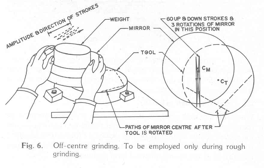
It is not important that the 1200 rotations of the mirror and the 450 rotations of the tool be precise; Only try to keep these motion approximately uniform over the grinding operation. Try to keep the strokes, about 60 � 80 per minute, smooth and uniform and avoid jerkiness.
After 2-4 minutes of grinding one will note that the initial tearing /screeching noise becomes weaker and weaker as the carborundum is worn down into a paste of finer particles and worn glass. At this stage stop grinding, remove the mirror and place it face up on a table. Wet one of the pieces of cloth and clean both the mirror and another charge of 80 grit on the tool face and recommence grinding. This completes one wet.
The
nature of the grinding operation is such that the mirror on top takes a
concave surface while the tool below takes a convex shape. After about
1½ - 2 hours of grinding it is advisable to check the sagitta (depth)
of the mirror. Fig 7 shows how this may be done using a steel straight
edge (the edge of a good, steel rule or a combination square) and a small
rod, bar, coin, piece of drill bit or feeler gauge of the right thickness
( see section 1.4).
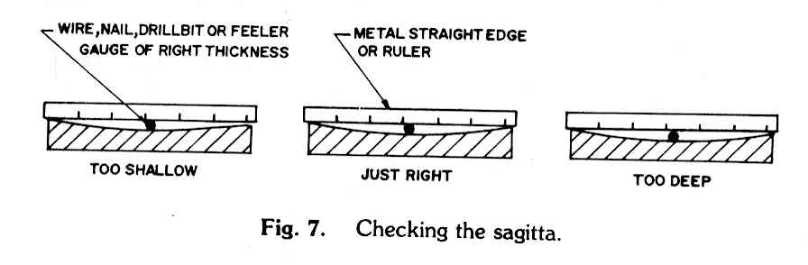
If the mirror is too shallow continue rough grinding (see next section,
hwoever); if too deep, invert the mirror and tool and grind with centred
1/3D strokes until the sagitta is reduced to the correct value; if just
right, stop rough grinding.
When the required sagitta is almmost reached it is advisable to finish rough grinding with a centred stroke. Let the mirror centre pass over the tool centre during the strokes and reduce the total amplitude of the of the strokes to 1/3D (i.e. about 5 cm for a 15 cm mirror). This will improve the surface shape to the spherical form that we seek.
If it appears during grinding that the edge of the mirror blank is not being ground, for example when ¾ of the required sagittahas been attained, it is advisable to start the shortened centred stroke right away and proceed grinding until the sagitta is obtained.
Depending on the weight used, the technique, the grit etc. the rough grinding of a mirror 12.5 cm � 20 cm diameter can be completed in 2-5 hours (with 12-15 wets per hour).
2.6 Fine grinding and smoothing
Once the rough grinding has been completed the mirror, tool, work plate etc. should be thoroughly scrubbed and cleaned using soap solution and an old tooth brush for example. If possible, the cleats should be replaced with new ones; the work post should be cleared, the newspapers and used cloth pieces thrown away. It is imperative that the coarser grit not contaminate the work area and lead to scratches on the mirror later on. Once the cleaning operation is complete, use new sheets of newspaper, tow new cloth pieces etc Then proceed with the grinding using the next grade, say 220 of grit.
As before, apply a thin coating of 1/8-1/4 tsp fo grit to the tool face just a few drops of water spattered from the finger tips. The mirror should not tend to slide off the tool : in that case the grit is too wet. the normal 1/3D stroke used is shown in Fig 8. the mirror is centered over the tool and the stroke is a W-type stroke with a total lateral amplitude of ¼D (i.e. 1.8 cm on either side of the centre for a 15 cm mirror) and an up and down amplitude of about 1/3D(i.e. about 2.5 cm up, 2.5 cim down for a 15 cm mirror). It should be 1/3D on the average; some strokes should be a little shorter and some a little longer. No attempt should be mde to make the strokes uniformly 1/3D in amplitude. The 1200 rotations of the balnk above and the 450 rotations of the blank below are of course continued. the wet now lasts longer, say for 4 or 5 minutes. At the completion of a wet the mirror and tool are cleaned as before and a fresh charge used.
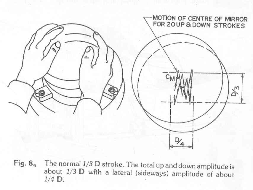
Starting with the 220 grit through the whole of fine grinding it is recommended that the mirror and tool positions be inverted every ½ hour or 1 hour. This will ensure uniform smoothing of the mirror and will leave the focal length unchanged.The weight can be dispensed with for all grades after 80 grade. From the 220 grit stage onwards till the end of polishing the normal 1/3D stroke is to be used.
After every hour of fine grinding and smoothing examine the mirror surface. When the pits left by the previous grade have all (or almost all) been removed shift to the next grade after a full scale cleaning operation. For the finer grades apply the grit, in the form of a thick paste, lightly and uniformly over the lower blank face with your index finger. Splatter a few drops of water and proceed. The wets will now last 5-8 minutes; use the normal stroke, the rotaitons and inversion of mirror and tool.
As a guide the following table shows the times that might be taken for each grade of smoothing for mirrors in the range D=12.5-20 cm.
Grade Time(hours)
220 4-5
340 2-3
600 5
800 3
1000 3
As a rule it is preferable to work longer on a given grade than shorter, before proceeding to the next grade of grit.
2.7 Testing the focal length and the mirror surface
After fine grinding for about an hour or tow with the 220 grade it is advisable to check the focal length of the mirror. Wait till the sun is high in the sky, wet the mirror face and focus the sun�s image, on a projection form the house; the distance from the mirror face to the focused image is equal to the focal length F of the mirror (see Fig.9).
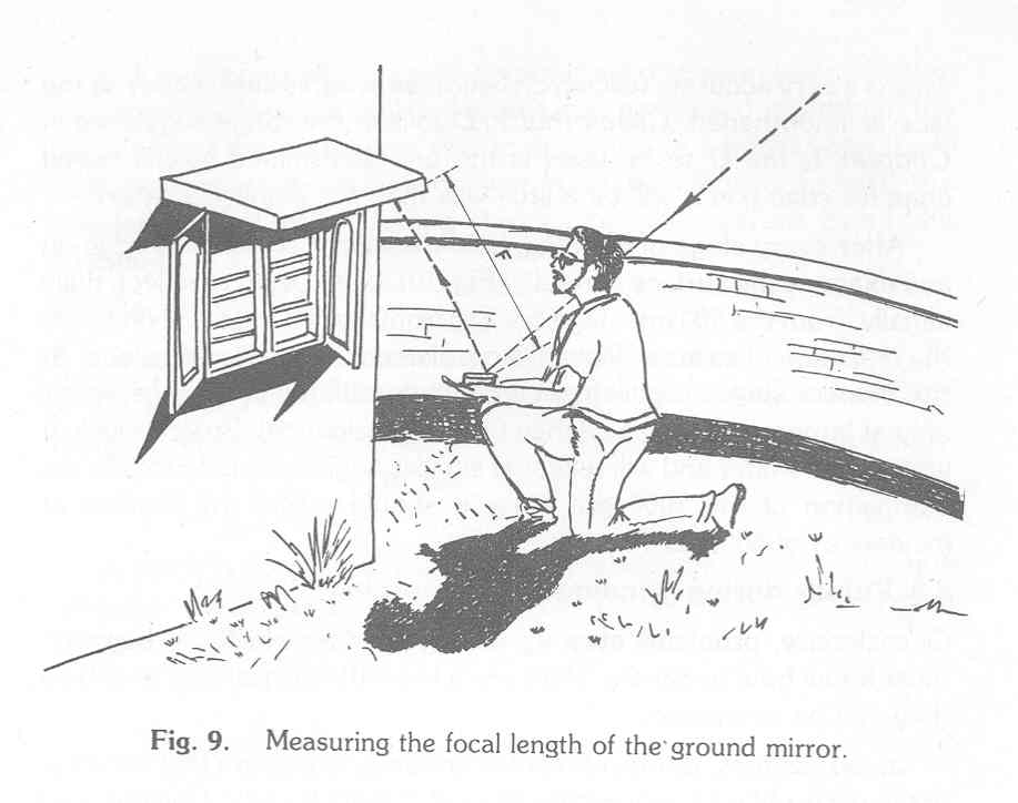
This is a very accurate test which becomes progressively easier as the face is smoothened. Check that F/D falls in the range suggested in Chapter 1; the D to be used is the one determined by the raised chamfer edge (i.e. it will be a little less than the blank diameter)
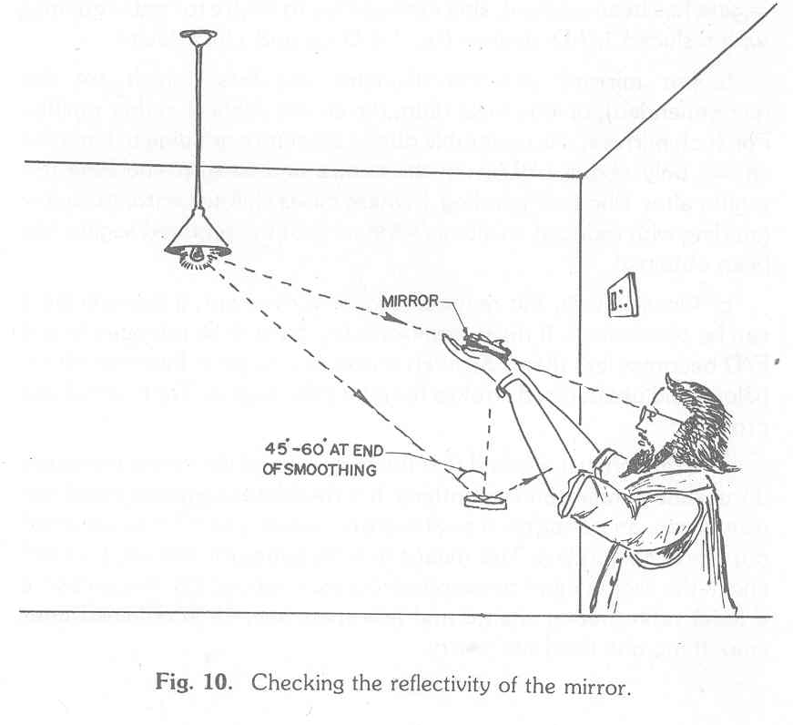
After every stage of grinding, hold the mirror so that it is edge-on and examine the surface carefully (fig. 10). It will begin to reflect, dully initially, form the 500 grit stage on. Try form the 500 girt stage on to see the reflection of an incandescent lamp filament from the mirror face. At the coarser stages the filament will appear dull red and will be visible only at larger angels of incidence (grazing incidence). Progressively it will appear whiter and will reflect at smaller angels of incidence. At the completion of the 1000 grit stage it should reflect the filament at incidence of 600-450.
2.8 Pitfalls during grinding and smoothing
Occasionally, problems crop up during grinding which the beginner must know how to handle. Here are a few with suggestions as to how they can be overcome.
Sometimes, during off-centre grinding, it appears that the dege of the mirror balnk is not getting ground. If more than ¾ of the required sagitta has been reached, shift immediately to centre to centre grinding with reduced 1/3D strokes (i.e. 1/6D up and 1/6D down).
For mirrors 12.5 cm diameter and less (which are not recommended), of long focal ratio, t he centre deepens rather rapidly. for such mirrors, it is preferable during off �centre grinding to keep the off-set only about 1/8D from the centre and to start checking the grinding with reduced stroke as soon as ¾ of the required sagitta ahs been obtained.
Occasionally, the required sagitta is overshot; if this is small it can be overlooked. If the overshoot is too great to be tolerated (e.g. if F/D becomes less than 7.5) invert mirror and tool (i.e. keep the mirror below) and use centred strokes to reduce the sagitta. Try to avoid this problem.
Frequently it is found that the focal ratio of the mirror increases duing fine grinding and smoothing. It is therefore suggested that if one wants, say an f/8 mirror a sagitta corresponding to f/7.5 be obtained during rough grinding. This means that the gauge (or wire etc.) used to check the sagitta must correspond to a focal ratio of 7.5. In any case, if a focal ratio greater than 8 and less than, say, 10 is obtained after smoothing one need not worry.
If one is careless during the smoothing operation and allows the wet to last too long the tool and mirror may get locked together. If this happens put the mirror and tool under water in a bucket and try to push tem apart; if this does not work try tapping the tool edge with a wooden mallet while holding the mirror. It�s best to avoid this situation.
It is strongly recommended that a complete record be kept of the mirror grinding operation. It could be in the form of a table as follows :
Date Grit Size
No.of hours
No.of wets
Comments
In fact it is suggested that a file or notebook be kept for the whole
telescope making project. It is from records and books such as these that
we can learn and improve our technique.
|
3. Polishing |
The polishing operations quite similar to the smoothing operation except for one important difference: smoothing is done by grit or emery, free to move between the tool and mirror, while polishing is done by rouge particles embedded in a pitch lap which takes the shape of the mirror surface.
The solid pitch should be such that it can be chewed or bittern; when a finger nail is pressed into a piece the impression should not form too easily; it should neither be too soft nor too brittle. Various authors recommend various proportions in the pitch/rosin/wax mixture e.g:
100% pure pitch alone (Texereau, 1963)
90-95 % pitch + 10-5 % beeswax (Ellison in Ingalls, 1976)
49% pitch + 49% rosin+2% beeswax (Yeagley in Page & Page, 1966)
Beeswax tends to make the pitch easier to cut and handle (Ellison) while rosin tends to make it hard. Depending on the pitch available and its quality when cold add as much rosin as necessary; a small amount of beeswax will do no harm. The author of this book normally adds about 15-20 gms of beeswax and 70-80 gms of rosin to about 350-400 gms of pitch. For mirrors 20 cm in diameter or less, 200-500 gms of the mixture will normally be more than sufficient.
Once the choice of pitch lap to be used (section 3.2) has been made use a stove to melt the pitch, rosin and wax in a tin or pan with a handle, stirring all the while with a stick or ladle. Do not allow the mixture to boil; when ready, pour the mixture over the tool or into the mould. If the pitch is dirty it is a good idea to strain the hot mixture through a fine nylon mesh or coarse cotton cloth. The mesh could be held by stout ring with a handle or by some other means.
3.2 Preparing the pitch lab (pitch tool)
There are many ways in which the pitch lap or tool can be made. We shall consider two methods. Assume that the work post has been completely cleaned as have the mirror, tool, work plate etc. Have a small plastic container of rouge solution at hand. It is preferable that this rouge solution be a little thick
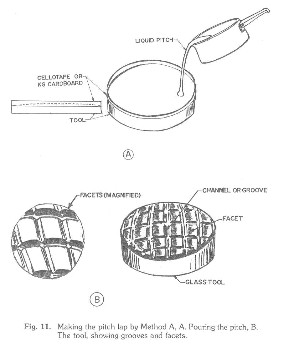
Method A: Take a strip of celotape or KG cardboard or thick paper and stick or wrap it around the edge of the tool so that the top edge of the cellotape/cardboard/paper strip is 6-7 mm above the top edge of the tool (see Fig. 11A). Pour the hot, liquid pitch mixture over the tool, covering it to a depth of 5 to 6 mm. While the pitch is still hot, but semisolid enough for the cellotape to be stripped away, strip away the cellotape, wet the pitch lap by dipping it in water and place the tool, face up, on the cleaned work plate between the cleats. Wet the surface of the mirror and press it face down on the tool, first making contact at one edge and driving the air out as the other edge is pressed in. The mirror should be centred and the pressing hard enough so that the whole mirror face makes contact with the pitch lap. A heavy weight (4 �6 kg) could be used in addition to body force. The pressing is repeated 2 or 3 times in 3 � 5 minutes until good contact is made all over. Now using a sharp knife or sharpened hacksaw blade, preferably heated slightly, trim off all the excess pitch that has flowed near the edge of the tool. The trimming should be such that the diameter of the top surface of the pitch lap is less than the diameter of the mirror (based on the chamfered raised edge).
After good contact has been made between mirror and too, groves have to be cut in the pitch face (see Fig. 11B). The groves can be 2 cm � 2.5 cm apart forming approximately square facets between them. The groves should be V-shaped, about 2-3 mm across on top, and can be cut out of the pitch lap when warm, using a ruler and a sharp blade or knife dipped in soap solution. The groves can also be melted out using a heated hacksaw blade or using a V-grooved tool attached to a soldering iron (Page and Page, 1966). The grooves should ideally reach the glass surface of the tool; take care that the centre of the pitch lap does not coincide with the centre of a facet.
After the grooves have been cut, retrim the edge of the lap and repress the heated lap on the wet mirror face to ensure that the contact is good. Finally, take a square piece of nylon mesh (used for mosquito netting), wet it with rouge solution, stretch it over the mirror face and press with the pitch lap (slightly warmed perhaps) until all the facets are criss-crossed with small groves formed by the mesh. Strip away the mesh. If all the facets are not marked, keep pressing, slightly heating the tool over a flame if necessary, until this is achieved. It is very important that there be perfect contact between tool and mirror; a uniform mesh finish assures this. After a further cold press, the pitch tool is ready for use.
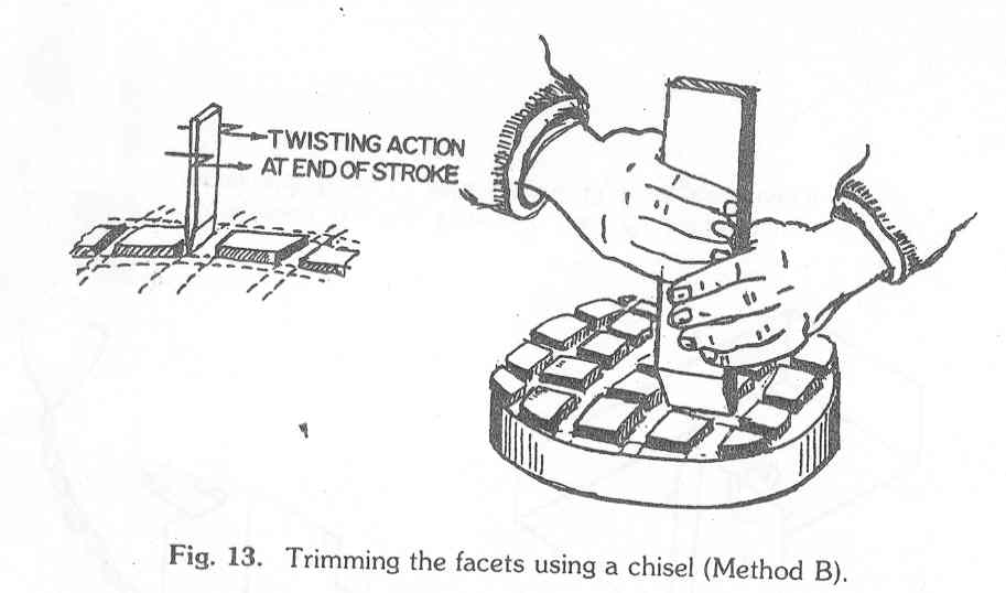
Method B: In this method, discussed in detail by Texereau (1963), the pitch misture is first cast into strips, next cut into square facets and then stuck onto the beeswax coated tool. The whole technique is illustrated in Fig. 12. First prepare the pitch mould from a flat plank of wood say 22 cm x 32 cm) and wooden sticks about 10 mm x 10 mm in section. Both the plank and the sticks should be covered by brown, school wrapping paper with the shiny side outside. Do not nail or tack the sticks too firmly into the plank, otherwise removal will be difficult. Pour the melted pitch mixture into the channels (which are 20 mm wide) to a depth of about 6 or 7 mm; the tray should rest on a flat level surface. While the pitch is cooling, carefully wash and dry the glass tool; mark the tool with dark pencil, the channels being of 6 mm width and the facets 20 mm x 20 mm; note that the centre of the tool does not coincide with the centre of a facet nor is it in a channel. Once the tool is marked, take a flat stick or wooden ruler about 20-25 mm wide and wrap around one end some cotton cloth so that 5-10 mm of the cloth projects beyond the end of the ruler; tie the cloth firmly to make a makeshift brush. Now melt about 50 gms of beeswax in a small tin or pan until it is quite fluid; dip the cloth end of the makeshift brush into the liquid beeswax and coat the tool face with a thin coat of beeswax. This should be done rapidly and as uniformly as possible; the pencil markings on the tool will be visible through the beeswax coating especially when held against light.
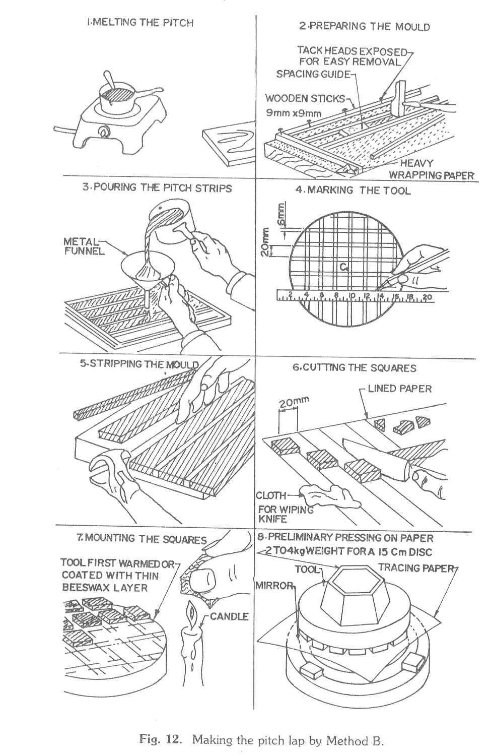
In order to strip the pitch from the mould the pitch will have to be quite cold. This will take a few hours. The stripping is much easier if the mould is kept in an ice box for 2 to 3 hours; if you do not have a refrigerator try to get a roadside ice cream vendor to keep it in his ice box for a few hours. Once the mould is cold, use a small knife to make long cuts on the paper wrapped around the sticks; use a chisel or knife to lift the whole mould, including the base wrapping paper, from the wooden base. Then sharply strip away the brown paper from the base; next gently ease out the sticks from their wrappings by twisting them by hand or using a pair of pliers. The strips of paper can then be stripped to leave long strips of pitch about 20 mm in width and about 5 7 mm in height. The strips are cut into squares 20 mm X 20 mm using a knife warmed over a candle flame and then stuck onto the beeswax coated tool. When choosing facets for mounting on the tool, choose squares of approximately the same height; make sure that the bottom of a square has melted somewhat before pressing on to the tool face.
Once the tool has been built, trim the edge squares with a sharp chisel (of width 25 mm) so that no facet protrudes beyond the tool edge; facets less than, say, half the area of a full facet can be left vacant. Now hot pressing on thick tracing 9or drawing office vellum) paper has to be done. Wash and thoroughly dry the mirror face, place the mirror between cleats and place the tracing paper on the mirror face. Lightly heat the pitch lap over the stove flame and press the lap on the tracing paper using a weight and body force if necessary. Strip the paper and note how much contact has been made. Gently reheat and repress until all the facets tend to stick to the tracing paper thus showing good contact. During the process some of the channels will tend to close; trim the facets, so that all the channels remain open. When using the chisel, use a sharp vertical stroke to cut the pitch facet, with the vertical face of the chisel on the side of a facet; the chisel blade should reach the wax before a twisting motion releases the excess pitch. The pitch scraps can be removed using a small knife. If the pitch tends to stick to the chisel, scrape the pitch off using a small knife. The chisel can also be heated in a candle flame and then wiped with a cloth but then the blade should be cooled in water and wiped dry before use.
Once all the facets make contact, trim the edges of the tool and any outsize facets. Then press on nylon or cloth mesh as in Method A. After a cold press the tool is ready to use.
The experience of the author and his colleague in the ABAA is that Method B, through more time consuming, is far superior to Method A. The reason is that the channels, which permit the deformation of the facets and also allow the rouge solution to reach the whole lap, are so much better defined and are more easily kept open during polishing. Method A is to be used only if the worker is different about Method B or is somehow unsuccessful in using Method B (say in making the pitch strips).
3.3 Polishing
Once the pitch tool is ready, squirt some rouge solution onto the mirror face using an ink dropper place the mirror between the cleats on the work plate, place the pitch lamp directly on the mirror and cold press for 20-30 minutes with a heavy weight (say 2-3 kg for a 15 cm mirror) on the tool. Every few minutes rotate the tool gently to make sure that it does not stick to the mirror. At the end of the period, wipe the mirror face dry with a soft cotton cloth; shake off the excess moisture from the pitch lap. Now put 2 or 3 drops of rouge solution on the mirror face and commence polishing, with the mirror below, using the normal 1/3 D stroke (shown in Fig. 8), using 60-80 strokes per minute. Rotate the tool and mirror as in grinding and invert mirror and tool after every hour of polishing. It is a good precaution to place two layers of flannel or some such cloth below the mirror when it is below, to avoid astigmatism.
Keep a small plastic bottle of rouge water at hand and apply the rough with a dropper or children's paint brush when the mirror and tool begin to stick; these can be done without removing the top disc, which need only be slid slightly out of alignment. This type of wet may last from 8-12 minutes long. Don't use too much rouge water and stir before use. After a half an hour of polishing check that the tool facets are all uniformly coated with rouge; if not repress, heating the tool.
During the first hour or two of polishing the tool may only move jerkily over the mirror; this should improve with time to smooth motion. If even after an hour and a half the motion is jerky, do another hot and cold press before recommencing polishing. With polishing, the grooves in the lap of Method A will tend to close up; before the grooves are fully closed and in any case after every spell of 4 hours of polishing, recut the grooves, trim the edges and repress hot mesh and cold before recommencing polishing. With the Method B tool, do a full trim, using the chisel, after 1 hour of polishing; you will find the pitch easy to cut after the spell of polishing. After a trim, hot press on mesh and follow with a cold press before recommending polishing. A full trim after every 4-5 hours of polishing and a partial trim whenever some of the facets are dangerously close is advised (two facets should never be allowed to touch). After every trim a hot press and a cold press of 20 minutes duration is advised (two facets should never be allowed to touch). After every trim a hot press and a cold press of 20 minutes duration is advised.
As regards the edge of the tool it should be trimmed such that lap diameter is always slightly smaller ( say by 1-2 mm or so) than the mirror face diameter.
Occasionally problems crop up during the polishing stage which have to be handled using good sense. If one is careless the lap and mirror may get locked. Squirt rouge in the channels, keep the mirror below between cleats and try to press the tool tangentially until free; you might have to use a wooden mallet. The situation is best avoided by not prolonging the wets too much ( but do not stop too early as the best polishing action will be lost!). Sometimes, because of the asymmetry of the mirror or tool, or because of the loosening of the cleats, the blank below may move too much; fold small strips of thick paper ( e.g. Computer card pieces ) and jam them between the blank and one of the cleats. More seriously, one of the facets may come off in the Method B tool during polishing. If it is a partial edge facet it can be ignored. If not, clean the area (from which the facet came unstuck) and wipe dry. Reapply wax of sufficient thickness and restick the facet; the lap will, of course, have to be repressed.
It is advisable to polish in stretches of at least 1 hour duration, preferably more. Keep a record of the spells of polishing and examine the mirror surface every two hours or so. When polishing is interrupted, store the tool and the mirror face-up covered with a sheet of newspaper. When recommencing, warm the tool over a flame, hot press for 2-3 minutes using a weight; then cold press for 20-30 minutes before starting polishing.
If all is well the mirror should appear polished in about 2-4 hours
of polishing. If the edges or centre do not appear polished is likely that
the tool was not pressed enough. The recommended minimum hours of polishing
are as follows :
D Hours
15 cm 14
20 cm 18
After a few hours of polishing a dry mirror will reflect the filament
of an incandescent lamp onto the ceiling of a room. This is, however, an
inadequate test. It is best to continue polishing till at least the above
minimum times are attained. The testing can follow.
|
4. Mirror Testing And Aluminizing |
If a 12.5-20 cm diameter mirror of focal ratio f/8 or greater has been ground and carefully polished using good technique there is every chance that it can be aluminized and directly used without any testing. It may not be a perfect spherical mirror but, especially for the beginner, it is likely to be quite satisfactory for casual viewing of the night sky. On the other hand, as a matter of scientific discipline and in order to gain valuable experience that will be useful later, it is suggested that one does at least some testing, and possibly some retouching, before proceeding with aluminizing. The Foucault test is not a difficult test to perform; but it does take some time, experience and study to correctly interpret and use the results of the test. We shall use the test only to make sure that our mirror is approximately spherical, free of zonal aberrations; we shall not attempt parabolization. If after reading this chapter, or after reading this chapter and attempting the tests, the worker feels uncertain about his or her ability to interpret the results or retouch the mirror, it is suggested that the mirror be sent directly for aluminizing. Provided the worker has carefully followed the instructions given here, the chances are very good that the mirror, while possibly imperfect, will be quite adequate for a beginner.
4.1 The Foucault or knife-edge test
In its crudest form, this most remarkable and delicate test, requires only the following items which can all be easily made or assembled form junk:
A wooden support to hold the mirror vertically. An adjustable base for the wooden mirror support it optional but desirable.
A razor blade mounted on a wooden block.
A 12V/25W motorcycle lamp bulb or a small 220V/25/W mains bulb mounted on a wooden block with a small hole and a slit plate.
A flat, heavy wooden board to support the mirror holder and the lamp/blade assembly.
A long table or two stools/tables to support the mirror holder and the lamp/blade assembly.
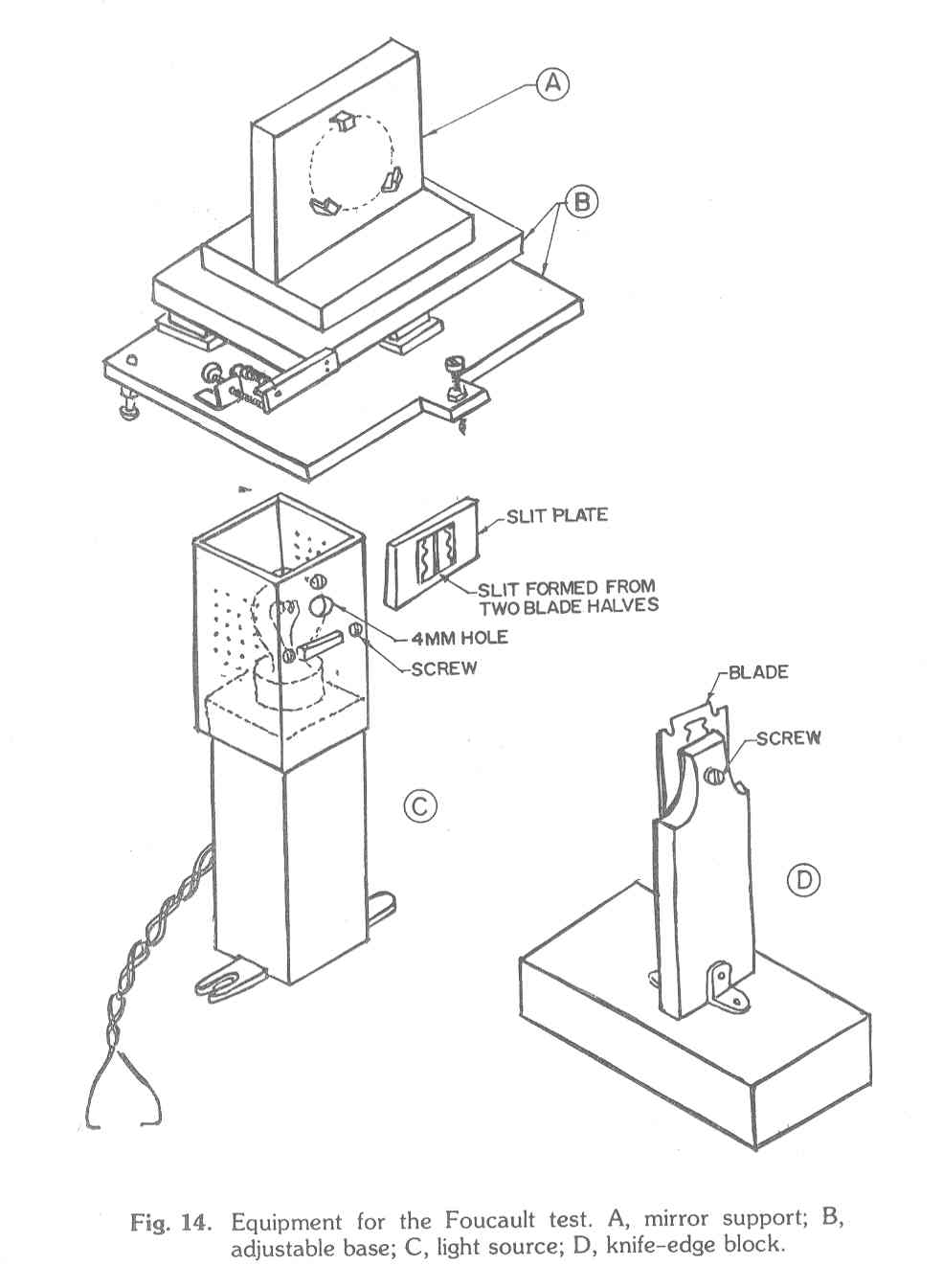
Figure 14 shows the construction of the simple pieces of equipment that are required. If the adjustable base is not used the orientation of the mirror support will have to be adjusted later using pieces of cardboard or paper. As regards the light source, if a motor cycle headlamp (12V/25W) is used one of the two filaments will be sufficient. The round 4 mm hole should be covered from the inside of the bulb enclosure by a small piece of ground glass (grind it yourself!) so that the effiective light source is diffuse. The adjustable slit plate has a hole greater than 4 mm which is coverd by two pieces of broken blade pasted edge to edge. The gap between the blade edges is a little less than 0.1 mm, say 0.06 � o.08 mm; exact gap width is not important but it is important that the edges be parallel. The slit plate can be made from a sheet of metal, plastic or wood. As regards the knife-edge block the orientation of the blade should be adjustable. The centre of the blade and the centre of the light source should be at the same height (say 12 - 15 cm) from the top of the wooden board supporting both of them.
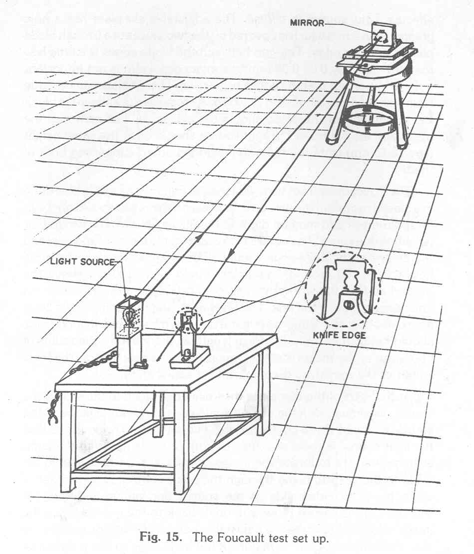
The Foucault test set up is sketched in Fig. 15. The test is best done in a closed room with no air currents present; the room should not be in total darkness and may be dimly lit by diffuse light from a window or neighboring room. The centre of the mirror, the lamb source hole and the centre of the knife-edge should all be at approximately the height from the ground; this height could be 90 � 120 cm above the ground so that the worker can sit comfortably in a chair behind the knife-edge to make the test. The knife-edge and the lamp should be at approximately the same distance from the mirror and this distance should be 2F (i.e. twice the focal length of the mirror = the radius of curvature of the mirror surface); recall that we already know the focal length of the mirror by the sun�s image test (Fig. 9).
At the start of the test place the knife-edge block to the side of the source, as shown, with the vertical knife-edge in the same plane as the source hole and 7 or 8 cm toits right. The slit plate is removed so that the light source is the 4 mm hole in front of the lamp. With the lamp switched on, try to locate the image of the source, which should be close to the vertical plane through the source, by moving a sheet of white paper to either side of the source and above and below it possibly; this is easiest done with one�s back to the mirror. Once the image is located operate the adjustable base of the mirror support so that the image falls on the middle of the knife-edge to the right of the source; if you do not have an adjustable base this will have to be done by carefully rotating the mirror support and putting pieces of paper or cardboard underneath it. Now move the white paper towards and away from the mirror to find the poition of the image (i.e. where it is most sharply in focus); if this position is more than 1 �2 cm in front or behind the knife-edge, move the wooden base (which supports the source and the knife-edge block) towards or away from the mirror until the sharp image is almost at the knife edge. The image of the source hole (which will be about 4 mm in diameter) should be only partially on the knife-edge and near its middle.
Now, sitting behind the knife-edge and with your, say, left eye as close to the knife-edge as possible try to visually locate the image. Moving the knife-edge block a little to the right, you should see the whole of the mirror face brilliantly illuminated. Now slide the slit plane over the source hole, making sure by looking directly at it, that the slit plate the source hole, making sure by looking directly at it, hat the slit is maximally illuminated. Now, keeping your eyes about 30 cm � 40 cm behind the knife-edge try to locate the bright image of the vertical slit which should be a little to the left of the knife-edge; once the image is located, rotate the blade on the knife-edge block until its sharp edge is parallel to the image of the slit; if the slit is too close to the source hole, slightly rotate the whole set up until the image is at the knife edge and parallel to it. Now move your head forward again until your eye is close to the knife-edge and image; the mirror face will appear fully lit but, naturally, less bright than earlier. Keeping your eye in this position move the knife-edge to the left (i.e. towards the source) so that it cuts the image of the slit from right to left.
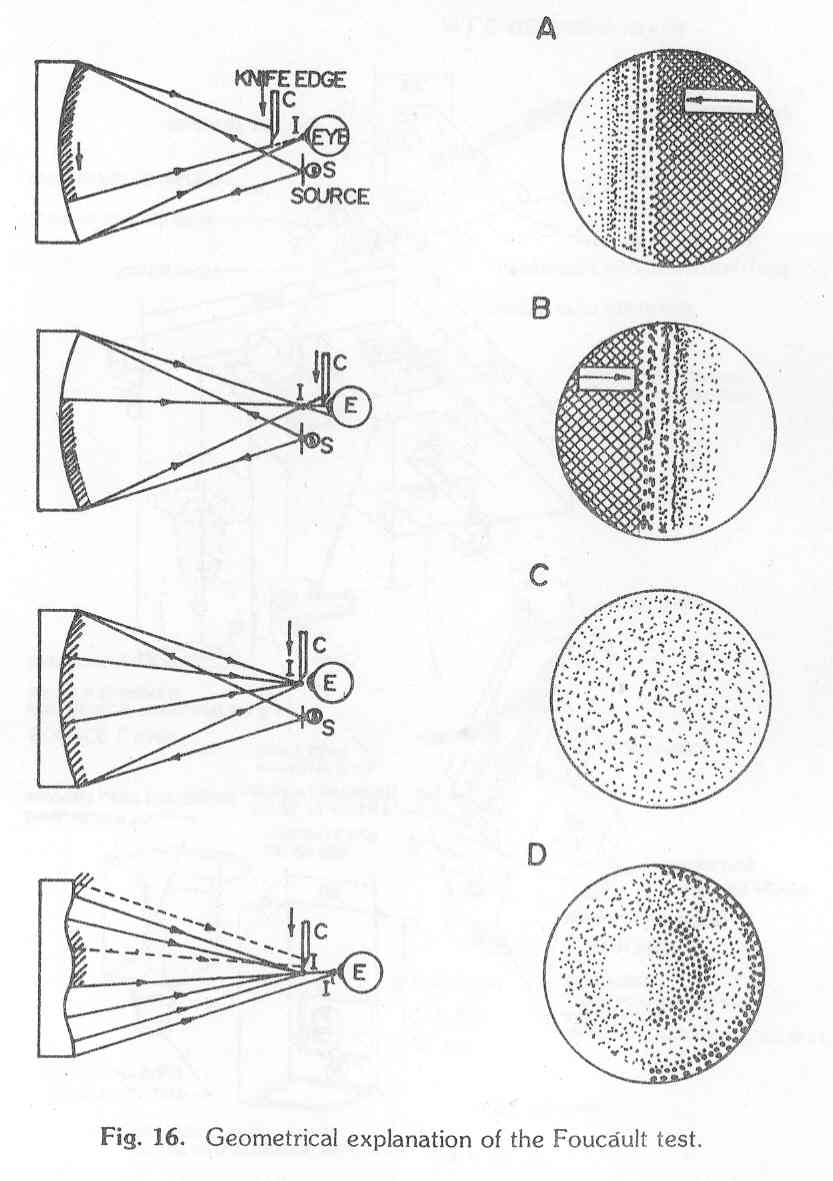
What we may see when the knife-edge cuts the reflected beam is shown in Fig. 16 (adapted from Texereau, 1963). Say the mirror surface was perfectly spherical; then Fig 16A shows that if the knife-edge is in front of the centre of curvature (i.e. closer to the mirror), the right part of the mirror would darken first as the knife-edge was brought in i.e. the shadow will move in the same direction as the knife-edge. For the present ignore the diffraction fringes in front of the knife-edge shadow. If the knife-edge is behind the centre of curvature Fig. 16B shows that the left side will darken first and the shadow will move in a direction opposite to that of the knife-edge. At the centre of curvature the mirror will darken uniformly as in Fig. 16C.
Usually the mirror is not perfectly spherical but will still be a figure of revolution. For example in Fig. 16D, the mirror has a raised central zone and a turned down edge. We will then see annular regions of varying brightness with the left and right half of the mirror being of opposite contrast; regions darker then the average on the left are reflected as regions brighter than average on the right. These can be understood from the ray diagram on the left.
In actual practice the view are not quite as unambiguous as the figures indicate. The shadow edge is usually not sharp and it takes some practice to locate the centre of curvature accurately.
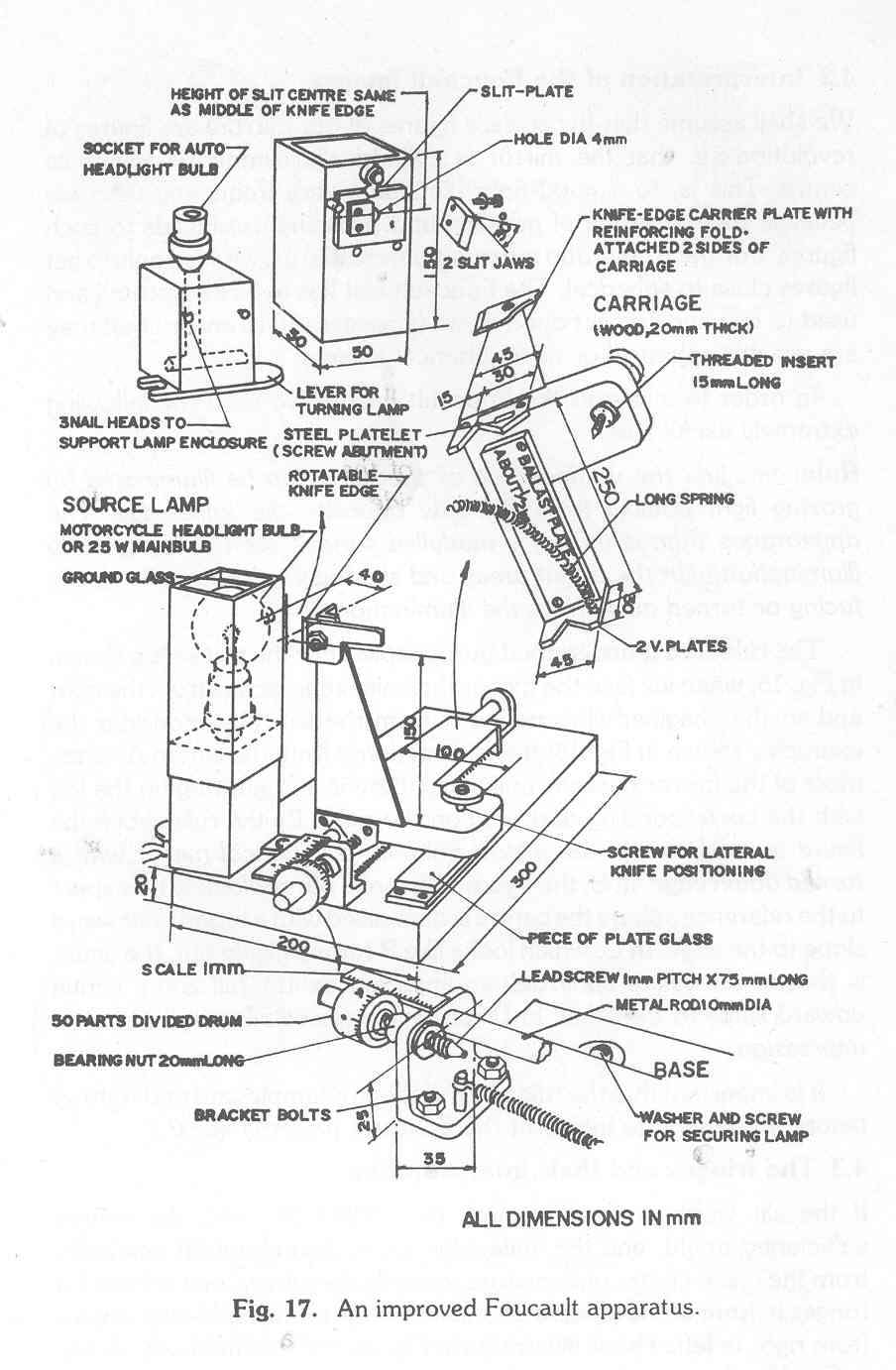
The set up described above is the crudest one can manage with. Improved, and hence more useful versions are possible with fine control movement of the knife-edge and facility for measuring its longitudinal position. Fig. 17 shows a useful set up which is not difficult to make. Such an apparatus would be essential for small f-ratio mirrors which have to be parabolized.
4.2 Interpretation of the Foucault images
We shall assume that the surface figures of our mirrors are figures of revolution i.e. that the mirror is cylindrically symmetric about its centre. This is, to a good approximation, very frequently the case because the technique of grinding and polishing used leads to such figures. For the high f-ratio mirrors of interest to us, we wish only to get figures close to spherical. The Foucault test has to interpreted and used to test and correct our mirror (if necessary) to ensure that they are usable spherical or near spherical mirrors.
In order to interpret the Foucault images we have the following extremely useful rule:
Rule: Imagine the vertical face of the mirror to be illuminated by grazing light coming from the side opposite the knife-edge. The appearance then is that of a modeled surface seen under grazing illumination with the bright areas and shadows indicating the slopes facing or turned away from the illumination.
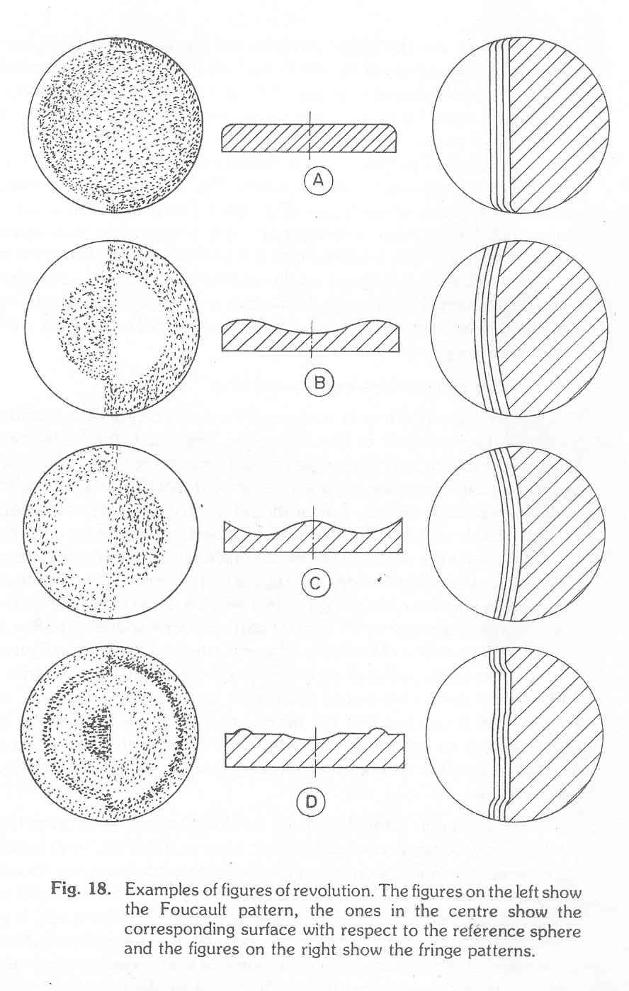
The rule is best understood by examples. For the test set up shown in Fig. 15, when we face the mirror the knife-edge moves from the right and so the imagined illumination is from the left. Now consider the examples shown in Fig. 18; the illumination is from the left. In A, when most of the mirror darkens uniformly there is a bright rign on the left with the corresponding dark ring on the right. By the rule above the figure is as shown in the middle column: a spherical mirror with turned down edge. In B, the figure is that of a paraboloid: with respect to the reference sphere the centre is depressed with a broad downward slope to the edge. In C, which looks like B turned inside out, the figure is that of an oblate spheroid: an apparent central hill and a gentle upward slope to the edge. In D we have a raised zone and a central depression.
It is important that the rule and the above examples are understood before attempting to interpret the Foucault patterns seen.
4.3 The fringe and their interpretation
If the slit width is small enough (say 0.06 � 0.08 mm), the source sufficiently bright, and the knife-edge more than about 20 mm away form the mean centre of curvature towards the mirror, on will see 2-4 fringes in front of the shadow of the knife-edge as the knife-edge moves from right to left. This is illustrated in Fig. 16 and schematically shown in Fig 18, where the fringe thickness is not shown. It turns out that for the amateur mirror worker the fringe patterns give a quick, qualitative picture of the overall mirror figure, less prone to misinterpretation than the Foucault patterns.
It should be clear from the above that good understanding, patience, careful work and experience are necessary for this fine stage of mirror making. It is better to be cautious and go slow rather than be hasty and spoil a good mirror. If for some reason the figure becomes terrible (e.g. the edge is badly turned down or the centre is hopelessly depressed) or the mirror becomes badly astigmatic (i.e. the mirror is not symmetric about its centre) the worker is advised to go back to the grinding with 800 or 1000 grit and repolishing; this is a very rare occurrence if the correct procedure is followed. Remember, too, that as delt here the test is only qualitative and one has to judge by the contrast of the light and dark areas how bad the zonal aberrations are. For the beginner there is the danger of being overcritical as the test is really quite sensitive; it is for this reason that the fringes are almost straight, stop work! At all cost keep thinking and evaluating during touch up.
The last few paragraphs may tend to frighten a potential mirror maker. This is unfortunate as there is no real cause for pessimism; one only has to be careful. Moreover, most mirrors ground and polished by the suggested techniques will work reasonably satisfactorily even if no testing or touch up are done; this is especially true if the work is done by a small group of people. The testing and touch up (if necessary) are suggested for discipline, understanding and improvement of the mirror. If after testing, you are not confident about interpretation or touching up, simply send the mirror for aluminizing; there is an excellent chance that it will work reasonably well.
Once the mirror has been polished its surface will have to be aluminized. It is possible, of course, to silver the surface; but this is not recommend as a silver coating tends to deteriorate rapidly with time. Aluminizing requires the production of a high vacuum, a capability beyond the resources of most amateurs. It is suggested, that once the mirror is polished, it be sent to a Government Laboratory or private firm with a request that the mirror be aluminized. One might try the Raman Research Institute, Indian Institute of Science, Indian Institute of Astrophysics or the National Aeronautical Laboratory, all in Bangalore.
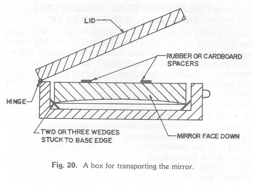
It is important that a good box be made for carrying and transporting the mirror. A suitable box is shown in Fig. 20; one could use a cardboard box, a biscuit tin or a styrofoam (thermocole) box but care must be taken that the mirror face not touch any thing. The mirror had best lie face down on wedges making contact only with the chamfered edge. Otherwise the aluminized surface may get scratched or otherwise damaged.
|
5. Telescope Tube, Mirror Cell, Diagonal And Eyepieces |
Once the mirror has been polished, tested and sent for aluminizing one has to fabricate the tube, mirror cell and supports for the diagonal and eyepiece. There is no unique design and one's choice is dictated by the materials and funds available. One should aim for a design which is rigid but light; one should also leave scope for changes and modifications that might have to be made after the telescope has been used for some time. Though must also be given to the method of mounting the tube onto the chosen mount (see Chapter 6).
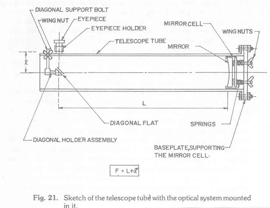
A sketch is given in Fig. 21 of the telescope tube with the optics mounted in it. At the right end a base plate, supporting the mirror cell (or holder), is bolted on the tube. The mirror cell, within which the mirror rests, is supported by three spring loaded bolts which permit the orientation of the mirror cell to be adjusted. At the left end are the diagonal support bolt, the diagonal holder, the diagonal and the eyepiece assembly. Note that the total length of the tube is approximately equal to the focal length of the main mirror. In Fig. 21 the mirror is shown seated inside the tube; if only a slightly undersized tube is available the mirror could be seated outside the tube but then the base plate assembly would have to be a little different. If the inside dimension of the tube is sufficiently large, say 30 mm more than the mirror diameter, the base plate too can be pushed inside the tube; a flange at the end of the tube is not necessary.
The telescope tube could be made of wood. PVC or even paper mache (paper pulp mixed with rosin etc. and moulded to shape); rolled sheet metal is to be avoided. The tube can be square or circular in section. The square tube has some advantages as regards fixing the eyepiece / diagonal assembly and the base plate; the circular tube has the advantage that it is often lighter and permits rotation in its cradle, a decided advantage with an equatorial mount.
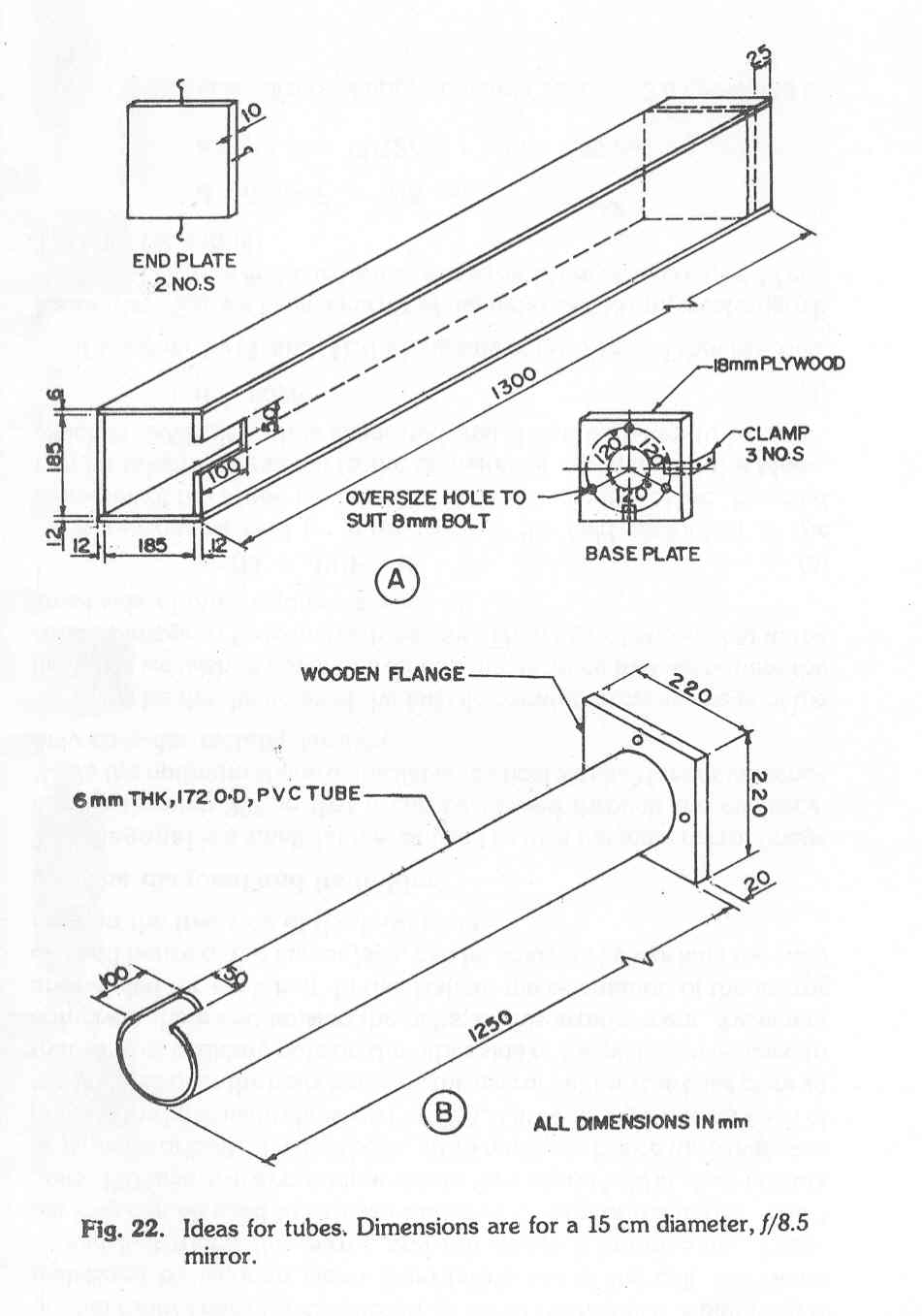
Fig. 22 gives a few ideas in this regard. The square wooden tube has 12 mm plywood planks on three sides and a 6 mm plank on top; the planks are nailed and glued, with resin glue preferably. In this design the base plate sits inside the tube, say 20-30 mm inside and is bolted onto the inside of the tube, say 20-30 mm inside and is bolted onto the inside of the tube using 3 clamps; there are two end plates one at each end to protect the mirror from dust and to cover the base plate respectively. The slot at one end is to permit sufficient play of the eyepiece/diagonal assembly so that focus is obtained at a convenient location. The tube is slightly longer than necessary and can be shortened, if needs be, once all adjustments have been made.
The PVC tube, of circular section, also has a slot at one end for adjustment of the eyepiece/diagonal assembly; the eyepiece and diagonal are then mounted on a built up cylindrical (curved) piece of PVC which will slide over the slot. The wooden flange could be attached using Araldite and small L-shaped clamps. A flange arrangement such as this is needed if the tube is slightly undersized for the mirror at hand.
The mirror cell must be such that the mirror rests in place subject to little or no stress. It is important for collimation that the orientation of the mirror face be adjustable; but this adjustment must be done not on the mirror face directly but on the cell which supports it.
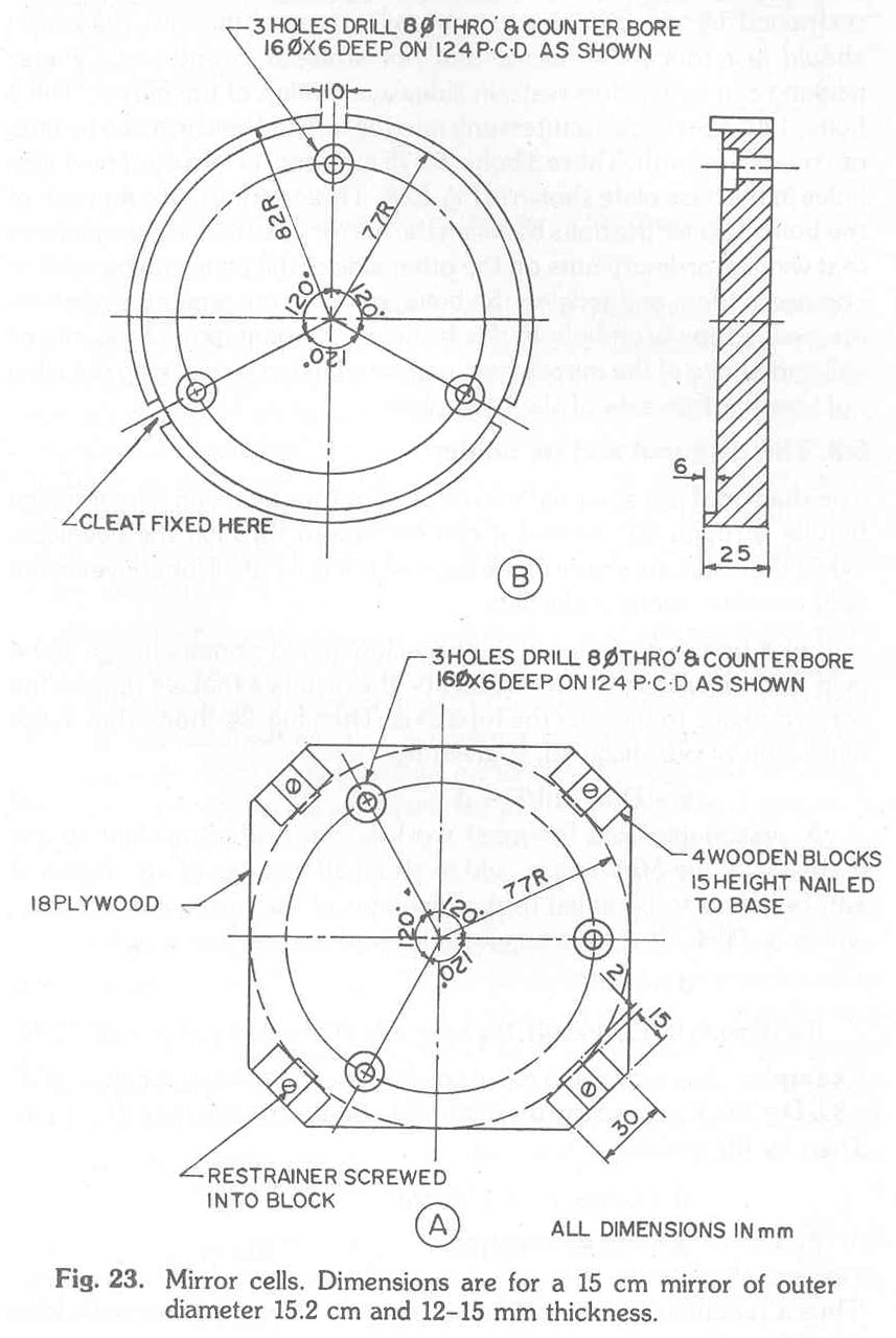
Fig 23 shows two mirror cell arrangements. In A, no turning is required as the mirror is held in place on the sides by 4 small wooden blocks nailed and glued to the cell base; B does require wood turning and is not really superior to A in any way. In either case the mirror rests on thin rubber pads (or cardboard) glued to the heads of 3 bolts and is restrained by wooden cleats from falling out of the cell; the cleats should just touch the mirror and not stress it in any way. Paper packing can be used to restrain sideways motion of the mirror. The 3 bolts, 1200 apart, are countersunk into the cell and held in place by nuts or Araldite or both. These 3 bolts, 60-75 mm long, fit into the 3 over size holes in the base plate shown in Fig. 22A. Three springs, one for each of the bolts, fit over the bolts between the mirror cell and the base plate so that wing or ordinary nuts on the other side of the plate can be used to compress them and tension the bolts; in this arrangement, 3 washers are needed for each bolt. In this fashion the orientation of the mirror cell and hence of the mirror face, can be adjusted by working the wing nuts on the free side of the base plate.
5.3 The diagonal and its holder
The diagonal is a small flat mirror used to turn the main mirror image bundle through 900 so that it can be viewed through the eyepiece. While the optimum shape for the flat is elliptical we shall for convenience only consider rectangular flats.
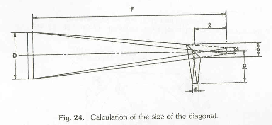
Let d be the diameter of the fully illuminated primary image of the field that we wish to cover and let l be the distance that we require the rotated image to be from the tube axis. Then Fig. 24 shows that a, the small side of our diagonal, is given by
a = (D-d)l/F + d
A reasonable field for most work is the field equivalent to the diameter of the Moon i.e. field of about 30 minutes of arc. Hence d can be taken to be equal to the diameter of the image of the Moon, which is .009F. It is suggested that d can be taken to be
d = 0.009F
If a is given by (3) and (4), the long side of the diagonal should=1.4a.
Example: Say we have a mirror of diameter D=15cm, focal length F=8.5
D=127.5 cm and say the image is to be 12 cm off axis i.e. 1=12cm.
Then by (3) and (4)
d=0.009 F=1.15 m
a=(13.85 x 12/127.5) + 1.15=2.45 cm
Thus a rectangular diagonal approximately 2.5 cm x 3.5 cm would be suitable.
For a quick look-see any small piece of flat mirror might possibly be used as a diagonal. But for any permanent arrangement any optically flat (correct to 1 wave length say) mirror is necessary if the primary mirror's quality is not be seriously degraded. The diagonal could also be ground and polished but tot save time it is recommended that a good diagonal of the right side be acquired from one of the institutions suggested in the section on aluminizing of from the ABAA (the Association of Bangalore Amateur Astronomers). Do specify the size when making the request.
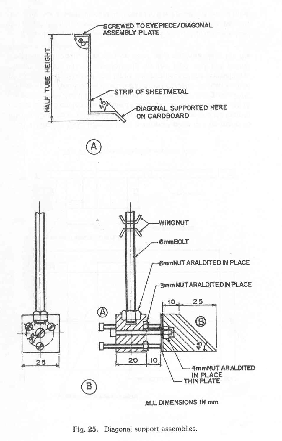
Once the diagonal has been acquired it has to be mounted in the tube. For this one needs a diagonal holder and support. A very simple diagonal support and holder would consist, Fig. 25A. of a suitably bent piece of narrow sheet metal. The diagonal could at worst be pasted on a cardboard which is then pasted on to the 450 ledge and the holder screwed onto the eyepiece assembly plate. A better arrangement is shown in Fig. 25B in which the orientation of the diagonal face can be changed by using the three 3 mm screws. The material used is wood. The central 4mm screw passes through a free hole in A and is screwed into B. The 3 mm screws are screwed into A and simply bear on B. The diagonal is loosely held in place by 4 small metal clips; it is always best to float the diagonal. If the diagonal is stuck in place there is the real danger of stressing it, which will lead to image distortion. The whole assembly is supported by a single 6 mm rod threaded at both ends, one end of which screws into the nut Araldited in A. The other end has two nuts (or wing nuts) to hold the bolt firmly to the tube or to the eyepiece/diagonal assembly plate.
Warning: when mounting the diagonal, make sure that the aluminized side
faces up! Otherwise, you may get multiple images at the time of viewing.
At worst a microscope eyepiece (10X) can be used for the telescope. It is however better to use a 25mm focal length. Ramsden eyepiece which is manufactured in India. Imported Kellner, orthoscopic and other oculars would be real luxuries; if and when these are produced in India they would be preferred to the simple Ramsden.
It is clear from equation (1) of Section 1.2 that the magnification
increases with shorter focal length oculars. Still, a beginner is best off using 25 mm focal length eyepieces; a clear wide field is preferable to a faint narrow field when one first makes observations. With experience and at a time when the whole telescope is being improved one can make provision for shorter focal length eyepieces.
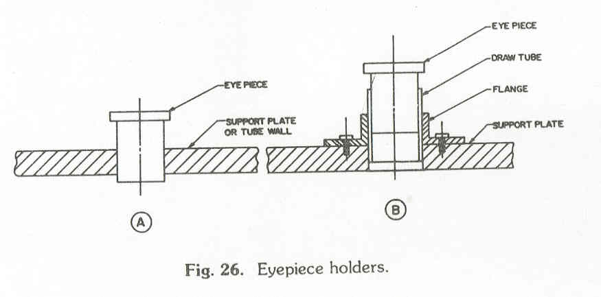
Fig. 26 shows ways in which the eyepiece can be held; in Fig. 26A the eyepiece simply passes through a hole in the supporting plate. In Fig. 26B the eyepiece is held in a draw-tube which moves in a flange fitted to the supporting plate. The parts could be made of brass, perspex or wood. Strips of KG cardboard or newspaper are often useful in keeping the eyepiece in place if the drae-tuber is too large or if the hole in A is oversize. It ought to be possible to move the eyepiece smoothly in and out for focussing; from this point of view a threaded assembly is most useful but involves machining.
5.5 The eyepiece/diagonal support assembly
As was indicated earlier the eyepiece and diagonal holder are best mounted together on a support plate, Fig. 27. The centre of the diagonal should be directly below the centre of the eyepiece draw-tube or hole. The support plate can be initially held in place by small nails or cellotape; after collimation and testing, once a satisfactory position has been located, it can be screwed firmly in place.
Fig. 27. Eyepiece/diagonal support plate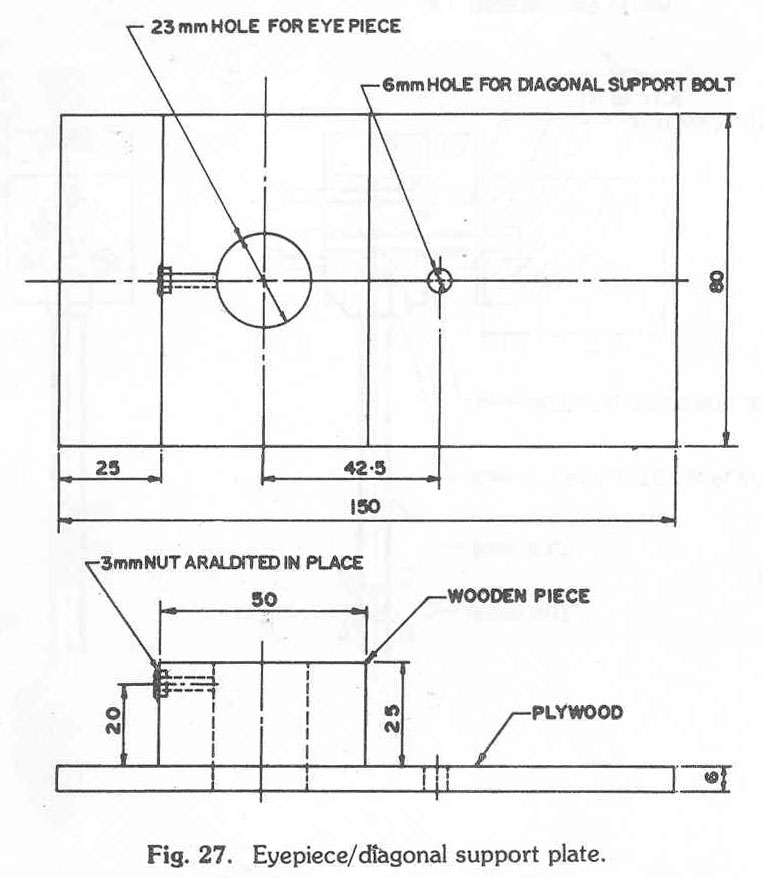
If a circular PVC tube is used a support plate can be made as follows. Cut one or two say 15 cm lengths of PVC pipe and slit them in half i.e. Two 15 cm lengths will yield 4 semi-circular sections of length 15 cm each. Paste 2 or 3 sections one on top of the other, using, say, PVC compound or Araldite; we thus have a 15 cm long semi-circular section of PVC with thickness 2 or 3 times the thickness of the original pipe. Moreover this will sit comfortably on the pipe and still permit longitudinal motion. This can be used as a support plate for the eyepiece and diagonal.
If should be pointed out that if one knew F accurately (as we indeed do) and if the mirror face is accurately located etc. then the diagonal and eyepiece assembly could be located in fixed positions on the tube.
The reason for suggesting the use of a movable support plate is that it permits one to be somewhat careless in the determination of the position of the mirror face etc.; the place can easily be moved to the optimum location. Moreover a movable plate permits changes in the design of the eyepiece and diagonal assembly without having to bother with the cumbersome tube.
|
6. Telescope Mounts |
The basic requirements of a telescope mount are:
It should provide for smooth movements of the telescope about 2 independent, preferably perpendicular axes.
It should be rigid and not permit unacceptable vibrations of the telescope tube.
It should permit the telescope tube to be statically balanced in all orientations of the tube.
Additional considerations might be portability, the ability to lock motions about one or both axes etc.
Most telescope mounts fall into one of two classes; altazimuth mounts and equatorial mounts. In the former, the two axes of rotation are the altitude (up and down) and azimuth (rotation about the vertical); in the latter, one axis, the Polar or right ascension axis passes through the Pole Star (Polaris). Theoretically, the advantage of an equatorial mount is that one can track a star over a long period of time by rotation about the polar axis alone. In practice, for most beginners: (1) the mounting is so unbalanced that plenty of friction is required to keep the tube stable and so smooth motion about one axis alone is not possible and (2) the tracking of a particular object occurs over such short periods of time that the theoretical advantage is hardly ever used. Thus for beginners either type can be safely used and the choice should depend primarily on cost, ease of fabrication and portability. Normally an altazimuth is cheaper and easier to make and use; it is certainly recommended for the beginner.
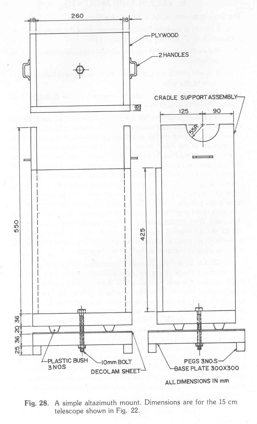
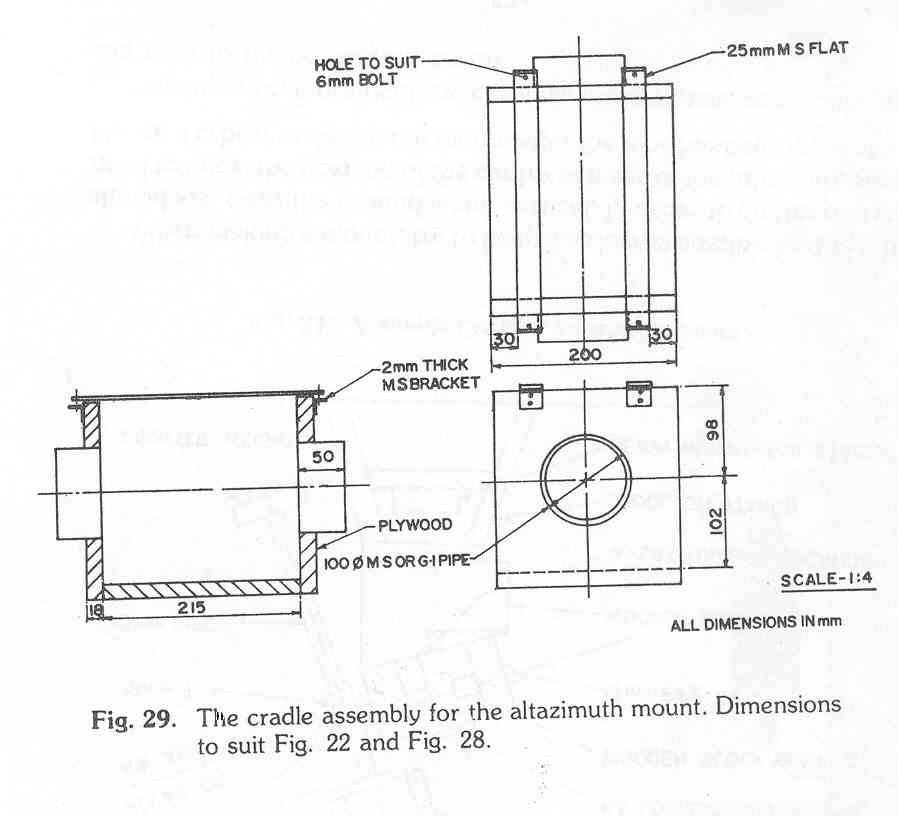
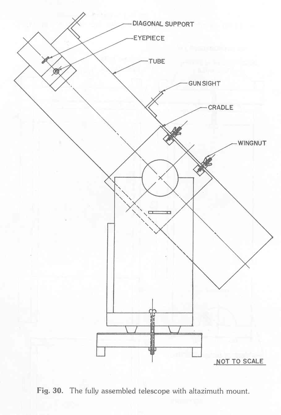
Fig. 28, Fig. 29 and Fig. 30 show the complete design and assembly of a telescope employing a simple altazimuth mount. This design is based onideas due to B. Kestner and R. Berry. The mount is fabricated from plywood and can be made using hand tools alone. The wooden boards are held together using nails, resin glue and wood screws. The 100 mm diameter are pipe lengths, which form the trunnions, seated in the semi-circular, slightly oversize cutouts in the side boards of the mount, permit the altitude of the telescope to be changed. The rotation of the cradle support assembly on the base plate permits asimuthal changes to be made; friction is reduced by using plastic bushes on a decolam sheet. Note that in this arrangement no counterweight is necessary for balance as the centre of mass of the tube is arranged to lie close to the axis of the trunnions of the cradle.
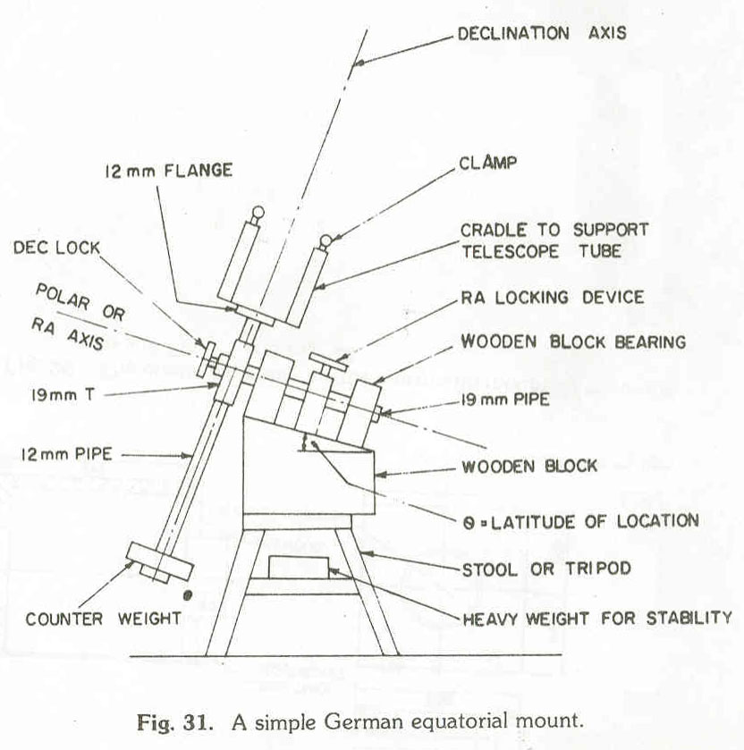
A simple German equatorial mount is shown in Fig. 31 which utilises pipe fittings and blocks of wood. The polar axis pipe should be welded or riveted to the T; the declination axis pipe is free to rotate in the T. Note that the slope on the block of wood allows the polar axis to point to Polaris when the stool rests on level ground. The counterweight must be adjusted so that it balances the tube weight about the polar axis. It will usually be found that a certain amount of friction in the bearings and from the locking devices are essential to hold the tube in position.
When making a mount, try to keep it as low as possible i.e. the tube should just clear the ground when vertical. In order to do this one will need to know the position of the centre of mass of the tube and optics. Hence it is best to design the mount after the tube has been fabricated.
For superior, more rigid and certainly more expensive mounts one can refer to the books referenced.
|
7. Collimation and the use of the Telescope |
Once the mirror has been aluminized and the tube and mount constructed, the optical system has to be properly aligned before the telescope can be used. During fabrication care should have been taken to (i) align the main mirror centre with the tube section centre, (ii) locate the diagonal centre at the tube section centre, (iii) centre the eyepiece holder over the diagonal centre and (iv) keep the eyepiece axis normal to the main tube axis. With the fabrication techniques usually used by amateurs these conditions would have only approximately been satisfied. Collimation or alignment of the mirrors will then help to make the telescope operational.
7.1 Collimation (Aligning the mirrors)
This is best done during the daytime with the telescope aimed at the sky or simply out of the window. It is also a good idea to do the collimation with the tube, not in its cradle, but just resting on a table or ledge. For a start fix the eyepiece/diagonal support plate, using tacks or sticking tape, at a position where you expect (by calculation and measurement) to get a focus, with the eyepiece halfway in its draw-tube or hole; the side of the tube holding the eyepiece support plate should be on top at this stage.
Step 1: Look into the open end of the telescope tube and adjust, if necessary, the 3 wing nuts on the bolts supporting the mirror cell so that you can clearly see your face.
Step 2: Remove the eyepiece from the eyepiece mount so that the diagonal mirror can be viewed directly. Keeping your eye centred over the eyepiece mount look at the diagonal and the images seen therein. The rectangular diagonal will look square in outline as it is seen in projection; in the diagonal will be seen the outline of the main mirror and by double reflection the image of the diagonal itself and the image of your eye. Usually, before alignment none of the images will appear concentric, as shown in Fig. 32A. Carefully identify the various images before proceeding.
Step 3: Adjust the orientation of the diagonal mirror so that the image of the primary mirror now becomes concentric with the outline of the diagonal mirror as shown in Fig. 32B. This adjustment can be done by using the 3 positioning screws shown in Fig. 25B or by bending the diagonal support if it is a simple metal strip.
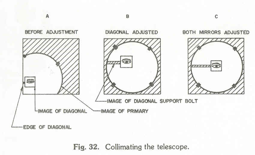
Step 4: Once the image of the primary mirror has been centred adjust the 3 positioning bolts supporting the main mirror cell, so that the images of the diagonal and your eye are centred with respect to the image of the main mirror and the outline of the diagonal. When the adjustment is complete the appearance should be as shown in Fig. 32C.
Once the above steps have been carried out the telescope should be ready for use. Now put the tube in its cradle and point the telescope at some distant object, say the window of a distant house or the top of a tall tower or tree. With the eyepiece in its holder try to first locate the object through the eyepiece and then try to get a focus by moving the eyepiece in and out of its holder. A beginner often has difficulty at this step because the distant object may be difficult to locate in the scope let alone focus. If you are not able to get a focus remove the tacks or tape holding the eyepiece support plane and slide it towards and away from the main mirror until focus is obtained with the eyepiece tube between quarter to half way in the support hole. When a pencil, mark the location of the eyepiece holder and tape or tack it in this position. Redo the collimation, if necessary, with the eyepiece/diagonal holder in this position.
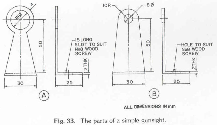
At this stage a gunsight had best be set up. The gunsight (Fig. 33) consists of two bent plates made out of sheet metal (tin, aluminum or brass) with holes in them for sighting. Part A is fixed near the open end of the tube on an edge of the plank adjacent to the plank holding the eyepiece (see Fig. 30); part B is fixed 400 � 500 mm away on the same edge. With the telescope in its mount, with the eyepiece holder at its position determined earlier, focus on a distant object; now look through part B of the gunsight and locate the same object with respect to the centre of the hole in A. Now move A to the left or right (note the slot in the base of A) and place strips of thin metal or packing either under A or B and then fix them in place so that when a distant object is viewed through the eyepiece the same object is seen at the centre of the hole in A when viewed through B. Now with the gunsight aligned, one only has to centre an object in the gunsight for it to be visible in the eyepiece of the telescope. One cannot overestimate the importance of the gunsight, for without it one will waste time hunting for the objects.
7.2 Setting up and using the telescope
When setting up the telescope make sure that the base of the mount sits firmly and correctly on the floor or ground. Make sure that the mount does not shake or wobble. If you are using a German equatorial mount align the polar axis of the mount with the Pole Star (Polaris); for casual observations this does not need to be done very accurately.
A beginner is advised to start by observing the Moon and planets and then proceed to stars, clusters and nebulae. Point the telescope at the Moon (use the gunsight of aiming) and try to see it through the eyepiece; once it has been located hold the tube in position, locking it if possible, and try to focus the image by moving the eye in and out. If the design and fabrication are correct it should be possible to focus the Moon with the eyepiece in its mount or draw tube. If not, it will be necessary to slide the diagonal/eyepiece mount towards the main mirror to get a focus. If this is done check that the collimation is maintained and correct if necessary. Realign the gunsight, if necessary.
Once focus is obtained, with the eyepiece conveniently in its mount, fix the diagonal/eyepiece mount permanently to the tube. After viewing the Moon, try locating and viewing Jupiter and its satellites, Saturn and its rings, Mars and Venus, and then cluster, nebulae and galaxies.
In a good telescope the edges of the discs of the planets will appear sharp and then stars will appear as sharp distinct points. Most amateur telescopes, especially first telescope, suffer from various defects such as coma, mild astigmatism and possibly poor figure. However, atmospheric conditions, especially for objects away from zenith (overhead), can also contribute greatly to poor viewing; in fact, sometimes the satellites of Jupiter display multiple images because of poor seeing (i.e. poor atmospheric conditions). So do not be despondent if on first viewing the images do not appear as sharp as you�d like them to be. Try out the telescope repeatedly and make the corrections suggested in the next section, if necessary.
What should one be able to see? With even a poor telescope the Moon should be a spectacular sight. The bands on Jupiter, its 4 Galilean moons, the right of Saturn, and the phases of Venus are all fairly easy on amateur telescopes. Moreover, with a reasonably good 15 cm diameter reflector one should be able to see almost all, if not all the objects in the catalogue of Messier. So very much can be done with your first telescope.
If for some reason you experience difficulty in getting a focus or if the images are not sharp etc., try the following:
Check the collimation.
Slide the eyepiece mount towards or away from the main mirror and try to get a focus.
If you have stuck the diagonal to its support, try floating it. Check the diagonal for astigmatism; when you do the collimation the image of your eye should not be blurred by vertical or horizontal lines. Change the diagonal if necessary.
Check that the main mirror is not held tightly by the restrainers.
Check the main mirror for astigmatism by rotation the main mirror and seeing whether the image changes.
Aperture the main mirror by making a ring of cardboard which covers the extreme 5 �10 mm of the mirror and fix it over the mirror cell. This will help if the edge of the mirror is turned down.
Try changing the eyepiece; a poor eyepiece, like a poor diagonal can spoil a good image from the main mirror.
If you are getting multiple images check whether the diagonal has been mounted incorrectly with the aluminized side face down; the aluminized side should face up.
7.4 Care and maintenance of the telescope
Like any other delicate instrument the telescope requires some care in its use and some maintenance every now and then. Make sure that the tube end is covered by an end plate and the eyepiece assembly is protected when the scope is not in use; otherwise dust and dirt will soon deteriorate the performance of mirror and diagonal. If the mirror is not going to be used for sometime it might best be left in its box. Obviously, the telescope should not be left outside unprotected. From the sun and rain.
No matter how careful you are, the mirror and diagonal will collect dirt and grime over a period of a few months. They will then have to be carefully cleaned. Ina basin, slightly larger than your mirror, pour some water, about enough to cover the mirror, and mix in some liquid detergent (like Teepol). Place the mirror under water in the basin, face up, and rock the basin so that the shallow waves clean the mirror face. Pour some liquid on some cotton, dip under the water surface and gently wipe the mirror face which is still under water. Pour out he soap solution and carefully rinse the mirror face with fresh water by rocking under water. After 3 or 4 rinses it is a good idea to rinse finally with distilled water if available. Gently shake off moisture from the mirror face and leave it to dry. A similar procedure holds for the diagonal.
After a few years the mirror will probably have to realuminized. At this time, or perhaps even earlier, the mirror can be refigured if it appears advantageous to do so. In any case, the beginner is well advised to use this first telescope for at least six months before he considers refiguring his mirror or building a bigger telescope.